CHARACTERISTICS OF HYDROFOIL BOATS
Boats, supported by the dynamic lift of hydrofoils, thus “flying” above the water, have been developed over the past 50 or 60 years (19).
THE BENEFITS of lifting the hull out of the water are twofold; most of the impact of sea waves is avoided, and resistance (drag) at higher Froude numbers, is less than that of ordinary displacement and even planing boats. Disregarding cavitation, higher speeds can thus be obtained with acceptable power and a minimum of discomfort for crew and passengers. Not counting experimental boats, the highest continuous speeds reached are still below 40 knots, however, in comparison to some 32 knots as in the transatlantic “United States”, for example, or some 35 knots in any modern destroyer. There have been two types of boats developed, using either surface-piercing self-stabilizing foils, or fully-submerged and artificially stabilized systems. A few examples are listed in the table.
|
hydrofoil boat |
foil system |
A (tons) |
/(ft) |
ВНР |
V(kts) |
vK/Af |
|
|
SupramarPT-20 (24) |
surf piercing |
28 |
68 |
1350 |
37 |
20 |
|
|
“Sea Legs” |
(23,b) |
submerged (o) |
5 |
29 |
220 |
26 |
20 |
|
US Navy PCH |
(20) |
submerged (o) |
117 |
116 |
6000 |
40 |
18 |
|
“Raketa” |
(19,d) |
submerged (•) |
2 |
88 |
1000 |
35 |
21 |
|
“Victoria” |
(20,d) |
submerged (o) |
39 |
65 |
2000 |
37 |
19 |
|
Canada“400” |
(24,d) |
surfpiercing |
200 |
151 |
20000 |
50 |
21 |
|
(o) autopilot-controlled (•) stabilized by planing plates forward |
TABLE, listing a number of built and operating hydrofoil boats. The weight (in long tons) is fully loaded, the engine power is maximum continuous installed, the speed is continuous cruising.
SIZE AND SPEED have been discussed in the first chapter. It should be noticed that the sizes of the boats in the table above, are quite small, that is in comparison to ocean-going ships. An equivalent to the Froude number is (Vk/n4). This number is for example:
We have also listed the Froude number in its usual definition. Both numbers show roughly the same ratio. Very instructive is the inverse of the square of the
Froude number, indicating that the loading (in pounds or tons) of the “United States” per square foot (or square meter), say of the plan form or bottom area of the hull, is roughly 20 times as high as that of the hydrofoil boat “Victoria”. This means that for equal speed or dynamic pressure, the hydrofoil area required to lift a ship such as the “United States” out of the water, would be in the order of 2 times its bottom area, in comparison to say 10% of that area in the “Victoria”. Since we need a certain aspect ratio for the foil (or foils) say in the order of A = bVS = 5, for efficiency, the combined span of the “Victoria’s” pair of main foils is roughly equal to the beam, while that of the “United States” would have to be V 20 =4.5 times the beam, which would be some 400 ft (or about 1/2 her length). In order to conform to the square-cube law about which this discussion goes, the speed of the “United States” would have to be increased to V = V 20 (32 or 36) kts, which is in the order of 150 kts. This is, of course, impossible. In conclusion, and as explained in (23,c) hydrofoil-supported craft are thus limited to small sizes, where may be in
the order of 20 ; and we see in the table above, how remarkably constant this number is among the boats listed.
|
MAXIMUM OR DESIGN SPEED У KNOTS
* SINGLE FOIL SURFACE PIERCING + SUPRAMAR – SURFACE PIERCING) 6 SUBMERGED SURFACE-CONTROLLED о SUBMERGED – SERVO-CONTROLLED |
0.1 I 10 100 1000
For points, see (23,c) Along tons
Figure 18. Statistical review of size (displacement weight in long tons) and maximum or design speed of operating or experimental hydrofoil boats (23,c).
If we assume that a number of 30 be the limit in the design of hydrofoil craft, their maximum feasible size would be in the order of 200 long tons for a maximum, hopefully cavitation-free speed of 50 kts. One way of increasing the size, is to increase the foil area S in relation to that of the hull (/ 4b’) or (4b’)2 where ‘b’ beam of the hull. Assuming that the boats listed above, have a foil span b = 4b’ (restricted, so that the boats can come along a dock or pier), doubling their span would increase the supporting area, and the permissible ship size (in tons) fourfold. At the same time, the beam of the hull would increase to = 1.26 times the original dimension, so that b/4b’ = 2/1.26 = 1.6. If this is considered acceptable from an operational point of view (24,f) the feasible size of subcavitating hydrofoil boats would be around 800 long tons. Such estimates and a statistical survey of existing or designed craft, are indicated in figure 18.
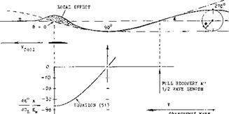
WAVE PATTERN. Regarding stability and control, the minimum number of foils required is two (as in airplanes), while the struts provide areas for lateral forces in turns and for directional stability and control. Considering the transverse wave system left behind a lifting foil (of larger aspect ratio and shallow submergence as in figure 8), it is theoretically possible to place the second foil at a distance downstream from the forward foil, where it rides so to speak, like a surfboard (but below the surface) somewhat ahead of the first wave crest. To say it in different words, the wave system produced by the second foil would possibly cancel the crests and troughs of the first one. The distance from the leading foil, at which the first crest is located, is 3/4 of the wave length
7’=2irV2/g (28)
and the distance x to the most favorable slope is 1/2 of this length. The corresponding Froude number is
= lMT = 0.56 = Vgx
or equal to 0.5, in an average trochoidal wave (3,b). Locating now the second foil at 1/2 of the wave length behind the first foil, we obtain a distance
x = (ir/g) v2 ^ 0.1 V2 in (ft)
where V in (ft/sec). At this distance the second foil would theoretically be propelled forward with a thrust equal in magnitude to the drag due to lift of the first foil (complete recovery). Considering a boat cruising at 35 knots = 60 ft/sec, the separation required would be x = 0.1 (60)2* = 360 ft. For comparison, the largest boat built to date (the AGH) has a length of 212 ft. Considering now a longer boat at 30 knots, we obtain tentatively x = 265 ft, hull length = 300 ft, but according to figure 18, a maximum displacement weight A ~ 100 long tons. Traditionally, the weight of a 300 ft long ship would be around 2000 tons. In conclusion, wave-drag recovery is not feasible in any practical design. Could it be of interest, however, to study the feasibility of “flying” hydrofoil boats in formation?
DOWNWASH. Deeply submerged, a hydrofoil would produce downwash in the same manner as the wing of an airplane. As explained in the “longitudinal” chapter, downwash has two components. The one corresponding to the wing’s circulation reduces quickly with distance from the lifting line at 1/4.of the chord. The other component is permanent; its maximum angle deep in the water (at the foil level) is
£ = 2 с<1= – 2CL/irA *=« – 36°Cl/A (29)
For A = 5, for example, this angle would be £ = —0.128 = — 7.6°, for C^ = 1. In keeping with the biplane theory, this downwash might be expected to be increased when placing a hydrofoil near the free water surface, in proportion to Kj in figure 9. Analysis of towing-tank tests
with tandem pairs of foils (21) reveals a different mechanism, however. First, consider the downwash relative to the water surface. Assuming that this surface is a solid boundary (a ceiling) the theory of ground effect (see in the “airplane” chapter) suggests a downwash angle
d£°/dCL = – 2 KgdSOVU^A) = – 36 Kg/A (30)
The ground factor (see chapter VII of “Fluid-Dynamic Drag”) can be approximated by
Kg= [30(h/b)3/2]/[30(h/b)3/2+l] (31)
According to this analysis, a hydrofoil produces a larger downwash angle when it is deeper in the water. This is experimentally confirmed (21,a) at the location below the first trough (where the wave angle as in figure 19, is zero).
|
Figure 19. Wave pattern and downwash angle behind a submerged lifting hydrofoil. The wave amplitudes are shown in exaggerated size. See also figure 8. |
(19) Reviews of hydrofoil boat development:
a) Oakley, State of Art, Aerospace Engg Dec 1962
b) Buermann 8c Hoerner, Naval Engrs J. 1964 p 191.
c) Buller, Status of Hy’foils, Interavia 1964 p 1692.
d) Soviet Hydrofoils, Interavia 1965 p 420; “Ra’keta”, Shipbuildg & Shipping Record of Sept 1958.
e) Hollenberg, Review, BuWeps 1960-53; AD-289,403.
f) Klante, USA Development, Schiff Sc Hafen 1964 p 347.
g) Yangos, Aeronautical Engineer on Hydrofoils, AGARD Rpt 473 (1963); AD-440,901.
h) Jane’s “Surface Skimmer Systems”, McGraw Hill.
i) Periodical “Hovering Craft 8c Hydrofoil”, London.
(20) Characteristics with fully submerged hydrofoils:
a) Miller, Hydrofoils, Nav Engrs J 1963 p 835.
b) Boeing, PC(H) Built for US Navy, Marine Engg Log Abstracts Feb 1964; AIAA Jc Aircraft 1966 p 79.
c) Hook, With Surface Feelers, The Syren Sc Snippg Jan 1959; Shipbdg Sc Shipping Record 1963 p 410.
d) Data NW Hydrofoil Lines 8c G&C (1966); see (22).
(21) Pairs of hydrofoils in tandem:
a) Kaplan and Sutherland, Stevens ETT Rpts 4C7, 410, 417,428,429(1951).
b) Wetzel, Interference, Univ Minn SAF Lab Rpt 61 (1962) 8c Paper 50(B) 1965.
c) Van Dyck, З-Foil Combination, Stevens Davidson Lab Rpt 975 (1963).
WAVE ANGLE. Part of the induced angle as in equation (44) corresponds to a deformation of the water surface. On the basis of (ll, a,b) it appears that at higher Froude numbers, the wave factor is
Kw = 2(KL-1) (32)
This factor determines the amplitude of the undulating wave train, while
Kj = Kw + Kg (33)
determines the “biplane” drag due to lift; and equation (45) the permanent downwash angle (under a ceiling as above a ground). Assuming that the transverse wave train be sinusoidal (only true for small amplitude), the wave angle (slope) corresponds to the cosine. In hydrofoil boats, or their foil systems, we are only interested in the first 1/4 wave length, beginning with a down slope at the forward foil, and ending with the first trough. This point is found (see figure 19) at the distance behind the first foil, equal to 1/4 wave length
x – 0.5 n V"/g 0.05 V2 (ft) (34)
where V in ft/sec. The point is important insofar as there will be no down or upwash due to the wave motion, at that distance. For example, for a subcavitating cruising speed of 35 kts = 60 ft/sec, the distance is 180 ft. As such, it would just be possible to be reached by the second foil in the tandem system of a larger hydrofoil boat.
WAVE DOWNWASFL In all realistic hydrofoil boats, we will have to deal with the wave downwash in the first 1/4 of the wave length. As illustrated in figure 19, the downwash derivative between the lifting foil and the distance x as in equation (50) varies as the cosine of the angle @ of the orbital wave motion, between zero and 90° . The maximum wave downwash angle (not including that due to the bound-vortex circulation) is expected to be
Є° = – 36 CL Kw cos © /А (35)
where Kw as in equation (15), and where cos© and t = zero, at the first trough (equation 50). For example, at 1, a hydrofoil with A – 5, flying at h = c, h/b =
0. 2, with K^ = 1.3, Kw = 0.6, will produce a maximum wave angle & => 4.3°. As a matter of interest, equation (49) is properly confirmed by 1.3 = 0.6 т 0.7.
ROACH. Another interesting point in the “wake” of a hydrofoil is the intersection of the two inboard lines originating from the foil tips. Since their angle is theoretically constant ( т or —19.5 ), the distance of the intersection is
x = ь VT (36)
where V~T — 0.5/tanl9.5°. This does not mean that a pair of lateral waves would meet there, thus forming a roach. As pointed out before, in realistic hydrofoil boats, the first transverse wave crest is at least one hull length behind the stem. The roach will then be between that crest and the stem, see figure 8.
|
A |
гг |
39 |
Ftons |
maximum loaded weight |
|
w |
= |
83.000 |
lb |
ditto, weight in pounds |
|
/ |
= |
65 |
ft |
overall length |
|
‘b’ |
= |
16 |
ft |
beam of the hull |
|
s |
= |
92 |
ft* |
combined area of 3 foils |
|
c |
= |
3 |
ft |
average chord of main fobs |
|
b |
= |
12 |
ft |
span of each of 2 main fobs |
|
A |
= |
4.0 |
– |
aspect ratio of main foils |
|
Ai |
— |
4.7 |
– |
ditto, considering end plates |
|
h |
= |
5.5 |
ft |
foil submergence when flying |
|
V |
= |
35 |
knots |
cruising speed |
|
V |
– |
60 |
ft/sec |
ditto, in ft/sec |
|
c |
= |
8 0.25 |
– |
design lift coefficient (cruising) |
|
■P‘ |
– |
3.000 |
ВНР |
maximum continuous combined of 2 |
|
D |
= |
0.1 |
w |
when cruising (calm water) |
|
vi |
– |
18 |
knots |
speed w’hen taking off |
|
CL |
= |
0.9 |
– |
at takeoff (just flying) |
|
n |
— |
75 |
– |
number of passengers |
|
THREE FOILS. |
A combination of three foils as in the |
|
A TYPICAL HYDROFOIL BOAT might be the "Victoria” (20,d). Characteristics are as follows: |
|
“Victoria”, each supported by a single cerural strut, has advantages as follows. |
a) The foils can readily be retracted by swinging them sideways, and lengthwise respectively, particularly in the “airplane” type configuration where the single rear foil may swing around the transom.
b) In the canard configuration (as in figure 20) the forward foil controls the height (altitude), while flaps in the pair of main foils make corrective motions.
c) Speaking summarily, the induced and/or wave drag of one of the 3 foils might be recovered.
Towing tank tests were undertaken (21,c) on the 3- foil configuration of the “Victoria”, as in figure 20. The two main foils are hopefully located within the up – w? ash areas outside the span of the control foil forward. Indeed, while the induced “lift angle” of one main foil tested alone, is 5.Ґ there is some reduction due to up – wash, that is down to 3.9° . Another test у elds a differential of 1.0° ; the average is 1.1° . It should be realized, however, that the angles discussed are those of the whole system pitching in unison. When considering the control action of one of the 3 foils alone, its lift-curve slope will essentially be that of an isolated foil (with dctf/dCj_ *= 15.6° , or dC^/doi0- 0.064, or doC/d6 = 0.55, in each of the main foils, for example).
|
|
MAIN FOIL. Since the transverse wave system is a function of the Fronde number, the above results only apply to the number based on longitudinal distance x, between canard and main foils
F = V/VgT = = 54/V32(38i – 1.54
where the first set of values applies to the 1/10 scale model, while the second set represents full scale conditions at V = 54/1.7 – 32 kts. ln terms of VT the dis- tance is x – 0.013 V4" (in ft). In figure 19, we are thus at x/0.25/ – 0.013/0.05 -0,26, where the wave down – wash angle is comparatively large. For a full-scale submergence of 5.5 ft (to the foil level) and an aspect ratio of the forward foil A{- 4.7, the down wash angle (in the vicinity of the center line) is estimated to amount to dS /dCu – — 6.0 . Considering now a continuous main foil, obtained by joining the two main foils together at the centerline, their induced drag would tentatively correspond to an average down wash angle of dS°/dCf_ – (1.0 +• 1.0 — 6.0)/3 — —1.3°. For an aspect ratio A, = 2(4.3) – 8.6, with a submergence ratio h/b = 0.23, the induced drag of the main foil (pitching together with the canard foil) would be
dCo і / dC c — (К; / tr A і – (d £/ dCe)
= (1.25/27) f (1.3 fr/180) – 0.069
For comparison, the pair of split main foils alone, has 0.078; and the whole foil system together would have 0.072, instead of 0.065 as for the З-foil configuration. The increment is (0.072/0.065) — 1 – 11°V When cruising at C^== 0,25: the increment would be in the order of 3°^of the total drag. In conclusion, the advantage of a split main foil lies in its convenient retractability as well as in reduced drag.
TAKEOFF. A situation where lift and drag due to lift are strongly involved, is takeoff. A hydrofoil boat is a more or less constant-angle-о Fan aek type of a vehicle. So far, trail і ng-edge flaps have not seriously been used to increase maximum lift. In automatically controlled systems, the flaps (or possibly the whole foil) are deflected, however, particularly at lower speeds and during takeoff. Maxim urn lift coefficients obtained in this manner, are up to С^= L at the moment where the keel leaves the water. Taking the “Victoria” as an example, the induced or due-to-lift angles of attack required, will then be as follows:
|
F i. gu re 2 0. T h e 3 – f о і ‘ v м г – і і і о і t Ь е ; * – г і г і or і а” (20,d) seen from belc », tested in a towing lank (2Lc) |
 a) The biplane-type angle (equation 20) with a К Value (fig 9) for twice the submergence h as in cruising condition. For Щ = 1.03, and Ay – 4.7, the result is Ы{ – 4.2° , instead of 4T° (as for an unlimited field of flow), and CD*L — 4.2 tr /180 •— 0.073, instead of 0.071, for an assumed (3 — 1.
b) The transverse-wave angle as in equation (14). Considering that at takeoff (subscript t), – 0.5 V,
while ht = 2 h (where parameters without a subscript indicate design or cruising condition) the Froude number at takeoff = l/V g ht may only be 36% of that when cruising. In case of the “Victoria”, this number is = 36(1.7)/V 32 (5.5) = 4.6; and at takeoff, = 1.6. For such a small number, equation (14) is no longer applicable. Figure 30 in chapter XI of “Fluid-Dynamic Drag” indicates a
Aoc = 0.09 Kw(c/h)(180/ir) = 0.35°, where Kw = 0.25, — and c/h = 3/11. The corresponding maximum increment of drag due to lift corresponds to ACd = (0.25) 0.09 (c/h) = 0.006.
c) The additional angle required to make up for the reduced dynamic pressure at the lower panel of the “biplane” (equation 26). For Cp = 1, this angle amounts to Ac* = (5/tt)/3.7 = 0.43°; the drag increment is indicated by AC^ = 0.43 (тг/180) = 0.007.
d) Regarding the angle of attack required to reach Cp — 1, equation (29) still has to be taken into account. The circulation-type increment of the angle is in the order of 0.6°. All the four increments are of the same order of magnitude. The combined value is Ac* = 1.5°, in addition to the “aerodynamic” oq —: 4.1°, for Cp 1.
|
14-
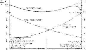
(00 flo (oO 6 0 $0 ioo LOAD ON HULL % -«*————————————————— ЮАБ ON FOILS % Figure 21. Drag of a hydrofoil boat similar to the “Victoria” (20,d) at takeoff speed, estimated on the basis of foil tests (figure 20) and towmg – tank investigations of the hull as in (2lx). |
SIZE-SPEED-SUBMERGENCE, Drag due to lift (which amounts to some 80°/° in the takeoff condition considered) may be more important than the angle of attack. This drag is increased to (0.094/0.079) -1.19 times the biplane value, as in (a) above. Total drag at takeoff is increased some 14°/°. — Considering now takeoff conditions in more general terms (but still at Cp= 1), it follows from equations (14)( 15) that
dCD /CDL = A<V/CVL ~ (C/Vt2) A1’3 ; Д<х ~ c A°’3A^
and from equation (26) that
ЬСь /Сь1 = Ьо(/Ы[ b/h; but A<x ^ c/h
We summarize these trends by saying that at takeoff, ACD~ Aoc is primarily:
ACd ~ c which means size of foils and craft,
AC^ ~ i/V£* which means low design speed,
ДСф ^ 1/h means submergence and sea waves-.
(22) The “Victoria”, designed by Gibbs &: Cox (New York City) for Northwest Hydrofoil Lines (W. I. Niedermair, Seattle, Wash.) built by Maryland Shipbuilding’ Sc Dry – dock Co (Baltimore) is operating between Seattle i Washington) and British Columbia (Canada).
(22) Performance characteristics of hydrofoil craft:
a) Hoerner, Takeoff, G&C T’Rpt 6 for О NR (1952).
b) Hoerner, Tests of “Sea Legs”, G&C Rpt (1958).
c) Hoerner, Size-Speed-Power of Hy’foil Craft, (26,b). (24) Hydrofoil boats of the surface-piercing type:
a) Von Schertel. Transportation (German & Supramar) SNAME Paper 1958; Am Soc Nav Engrs J 1959 p 603.
b) Biiller, Hydrofoil Boats, Ybk STG 1952 p 119.
c) Harbaugh, Development, SNAME Paper 2-h (1965).
d) Canadian EHE-400, Shippg World Shipb Aug 1964.
e) Lewis, For Canadian Navy, SNAME Paper 2-1 (1965).
f) The boat (d, e) has a foii-span/beam ratio of 3,
so that it resembles an airplane in planform.
(2d) Consideration of size Sc speed of hydrofoil boats:
a) See under “size and speed” in the first chapter.
b) Hoerner. S-S-P, Naval Engrs Journal 1963 p 915.
HULL LIFT. The lift coefficient Cp — 1, mentioned above for takeoff, is not necessarily the optimum (giving least drag). Rather, it is usually’preferable to let a planing hull carry some of the weight, to get over the hump in the drag/speed function. The optimum distribution of load depends very much upon the resistance characteristics of the hull. Depending upon the Froude number at takeoff speed, a suitable hull may be selected, tentatively with a length/beam ratio of 4. It is shown in figure 21, how hull resistance and hydrofoil drag vary as a function of speed. The resistance is taken from towing-tank tests on a hard-chine hull with charac- terists similar to those of the “Victoria”. An amount of AD/W = 2% is added to account for interference with the struts attached to the bottom. Starting point for the foil system is AD/W — 37b representing the fully (11 ft) submerged struts plus nacelles. The foil systems
drag due to lift corresponds to dCD /dC£ =0.065 +0.010, where the second component accounts for the increase of the viscous drag (including interference). As in other configurations, minimum combined drag is obtained roughly with 50°/° load (weight W) each on the hull bottom and on the hydrofoils. To get from the minimum (D/W = 10.5%) to the takeoff point (where the keel leaves the water, with 100°/° of the load on the foils) it is necessary, first to go to some 12% of drag. This is done by deflecting the control flaps of the main foils and the angle of the canard foil. The latter one can also be used to maintain the optimum angle of trim during the takeoff run (which is around 3° , keel against waterline). It can also be understood, that lift-increasing devices (special flaps) are not needed in hydrofoil boats. The induced drag would increase the hump drag (D/W = 120/c). Of course, acceleration both in longitudinal and in vertical direction, require some additional thrust, not thinking of sea waves against which the boat may have to take off. In fact, the full-throttle thrust of the “Victoria” at 19 knots, is some 17,000 lb, which is almost T/W =20%. With a margin above the hump of some 6000 lb, the 87,000 lb of fully loaded weight can be accelerated by
TURNING. When turning, any vehicle needs a centripetal force Y to resist or balance the centrifugal force
Y = ‘M’vVr =2 W vVg d (37)
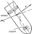
where ‘M’ =W/g =mass, and d = 2 r = diameter of the turning circle; see figure 22. In airplanesthis force is provided by a component of the wing’s “lift”, obtained by banking properly. In displacement ships as in airships, the lateral force is the lateral “lift” (or “resistance”) of the hull (including stem, rudder, vertical fins) as described in the “slender body” chapter. In hydrofoil craft, banking is theoretically possible. Indeed, the surface-piercing type is supposed to bank in a manner similar to that of certain more or less planing motor – boats (having a suitably dihedraled bottom). Most of the boats with fully submerged hydrofoils are turning “flat”, however, thus avoiding broaching of the outside foil tips (particularly in sea waves). In this case, the struts have to provide the lateral lift force Y. Solving equation (60) for the turning diameter:
d =2 r =2 ‘M’ V2/Y =2 V2/a = (2/g) vV(a/g) (38)
where the hydrodynamic force Y=‘M’ a, and a = lateral acceleration.
AT/W/g = 6000(32)787,000 = 2.2 ft/sec2
![]()
![]()
The control system can then be used (by way of an altimeter) to make the boat “jump” up to the cruising level, corresponding to a foil submergence of 5.5 ft. As pointed out in chapter XI of “Fluid-Dynamic Drag”, resistance then reduces; and the minimum obtained in the “Victoria” is D/W = 90/o, at 26 or 27 knots. At the maximum continuous speed of 36 kts, the drag ratio is D/W = 10% A speed of 39 kts can be obtained (in calm water) by re – ducing submergence to 3 ft.
-■5—— RADIUS г OP TURNING CIRCLE
 Figure 22. Geometry and forces during the steady-
state turn of a hydrofoil craft.
SURFACE-PIERCING hydrofoil boats, particularly of the Schertel-Supramar type (24,a, c) are at this time operating in larger numbers, in passenger-carrying services, primarily in sheltered waters. Considering, however, military applications in open, or at least in coastal waters, there is only a limited advantage in such boats, over conventional patrol or motor-torpedo boats, in regard to speed, stability and riding comfort in a seaway. To point out the importance of seakeeping in these and other hydrofoil boats, it may be mentioned that the world-speed record in so-called hydroplanes (gliding, riding or flying on 3 points over perfectly calm water) is around 200 mph (some 170 knots), while seaplanes are available, or could be built again, with minimum speeds,%y around 100 kts. In other words, the problem is to go continuously fast in water which is not calm, but may have waves up to 6 ft in height (crest to trough, as in sea state 4).
LATERAL FOIL FORCES are essentially proportional to the angle of yaw or sideslipping (which is a necessity in any turn). The required forces can be produced by struts, by dihedral of the foils, and/or by end plates attached to the foils. For the latter, see the “wing” chapter. Lateral forces of “V” shaped foils can be found in the chapter on “directional stability”, under “V” tails. Regarding surface-piercing dihedraled hydrofoils, a metacenter (the lift center) different from the one responsible for roll stability must be considered. This is indicated by dashed lines in figure 16. It is seen that in the particular emergence depicted, the craft is not balanced (it will heel outward). This type of boat has to slow down before making a turn, so that a larger wetted span is obtained. The lift center can also be raised by replacing the apex of the “V” shape by a horizontal piece of foil.
STRUT FORCES. Boats with fully submerged hydrofoils need vertical struts (with lateral area) for turning (and stability). As a tolerable level of acceleration in equation (61), a = 0.2 g may be assumed. Disregarding ventilation, a surface-piercing strut is a “lifting wing”, with the hydrofoil below acting as a large end plate. A pair of struts could also be considered to be not only a biplane, but even a “boxplane”. As an example, we will assume a single-strut configuration (similar to those of the “Victoria”) with dimensions as follows.
A =4.5 = aspect ratio of hydro foil
с = c = chord of foil and strut
h/b = 1/3 = foil submergence ratio h/c =1.5 = wetted aspect ratio of strut
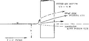
The surface flow pattern past a yawed, lateral-lift producing strut is a function of the Froude number Fc = v/l/fc. Within the range of high numbers (as we have them in hydrofoil struts) the theory of antisymmetrically twisted wings (28,d) predicts an effective aspect; ratio of the strut equal to that of the submerged part Considering the foil to be an end plate with (h/b) (strut)
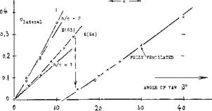
= (b/h)(foil) = 3, the effective ratio is theoretically doubled; thus AL = 2 (1.5) = 3. The flow pattern at the water surface shows some water piled up at the pressure side, and a depression (hollow) forming along the suction side. — Experimental lift coefficients of a strut are plotted in figure 23. Evaluation of these and other data (on surface-piercing foils) leads to the conclusion that a piece of the strut “at” the water surface equal to at least Ah or Ah = 0.10 c, is not producing lift (on account of spray?). This means that the effective area is reduced as well as the effective aspect ratio. According to the “wing” chapter, the lateral angle required, Corresponds to 0
d^/dC^t = 11 + (1 l/Af) + (26/Aj_) (39)
In a similar manner, for aspect ratios below unity (as in the “small aspect ratio” chapter):
dClat /dP° = 0-8 (i^/360)Aj = 0.022 Aj. (40)
for the forces of the strut. As seen in figure 23, the two equations describe very well the tested forces. Regarding the non-linear component of lift, it is reasoned that it cannot develop at the piercing point of the strut. This component might then be approximated by
ACl = sin2|i/A (41)
LIMITATIONS. It is seen in figure 23, that the lift (lateral force) of one of the two struts breaks down at (3 — 14°, from Claf = 0.3. This breakdown due to ventilation, is discussed in the next section. Other limitations as to turning, are the rolling moment to be balanced by “aileron” deflection in the hydrofoils, the effectiveness of the rudder(s) (attached to, or part of one or more struts), and the power required to overcome the increased drag (due to lateral-force-producing struts, aileron deflection, and foil-strut interference,
|
|
|
Figure 23. Lateral forces originating in a surfacepiercing strut, tested (28,b) at I^ — 9, and Rc — 4(10)^, in a towing tank. |
 |
||
 |
 |
 |
INTERFERENCE. The lateral-force derivatives (around = 0) of struts from two different sources, are plotted in figure 24, as a function of their submerged aspect ratio. The theoretical functions (equations 63 and 64) agree well with the tests on an airfoil-type section. A sharp-edged section evidently loses some suction lift. Considering a hydrofoil attached to the lower end of the strut to be an end plate, the Kj, factor as in figure 9 could be used to increase the effective aspect ratio. As shown by the pair of single points ( —) in figure 24, there are considerable interference losses, however, at the strut-foil juncture, thus reducing the force slope


