CHARACTERISTICS OF LIFTING HYDROFOILS
Boats equipped with hydrofoils – and thus “flying’’, with their hull out of the water, have been under development for more than 50 years. Characteristics of such foils have been analyzed and tested (in towing tanks).
SURFACE WAVES. Drag due to lift of fully submerged hydrofoils is explained at length in chapters X and XI of “Fluid-Dynamic Drag”. As long as
doCi/dq = dCDL /dCL (7)
the angle due to lift can easily be derived from the drag functions. First of all, there is a surface wave. Water piles up above the hydrofoil moving below, thus starting a transverse wave train (with crest and trough lines essentially parallel to the foil). In two-dimensional flow, an angle similar to the induced angle (see the “wing” chapter) is caused by lift in the presence of a free water surface. Based upon submergence h and area (b h), indicated by subscript ‘h a universal function is obtained (see chapter XI of “Fluid-Dynamic Drag”). For froude numbers Fh above 5, we obtain approximately the angle due to the wave, but at the level of the foil:
d<xw/dCLh =0.5Fh2 =0.5gh/v2 (8)
where w indicates “wave”. Considering Сщ = C (c/h), we find
<xj = Kw(0.5/fJ )(c/h)Cu(180/ir) (9)
The factor Kw = f(b/h) (as in chapter XI of “Fluid- Dynamic Drag”), approximated by
Kw=(b/h)°y4 (Ю)
always smaller than unity, accounts for finite foil span. We can also write
doc% /dCL = (Kw/f£)(90/tt) (I l)
2 2
where Fc =V /g c. For a given hydrofoil craft (with constant weight, and foil dimensions b and c) it is then found that
|
aw~iMh°’3 |
(12) |
|
—’ l/v6h0’3 |
(13) |
For all practical purposes, therefore, this two – dimensional wave angle can be disregarded at the usually higher cruising speeds of hydrofoil boats. See later under “takeoff”, however. An important aspect of drag due to lift is also the fact that most towing – tank tests on hydrofoils are done above the critical or wave propagation speed
Vw = VJU (И)
where H = depth of the water (to the bottom) of the tank (or possibly in a water tunnel). In short, “all” experimental results at higher speeds (and/or higher Reynolds numbers do not contain the two-dimensional type of wave angle and wave resistance (13)
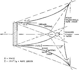
INDUCED DRAG and the corresponding increment of the angle of attack are as in airplane wings, a function of the aspect ratio A = b2/S. The surface of the water is deformed again by the presence of a lifting wing below. As shown in figure 8, a hollow appears on the center line of the wake, at x = 1.4 b. On the other hand, above the foil ends (wing tips), a pair of humps develops. Gravity distributes these humps in lateral directions, in form of 2 pairs of waves. Part of the “induced” drag can thus be called wave resistance. It can be said, however, that those waves are part of the trailing vortex system, partially transforming itself into trailing waves. At any rate, momentum is transferred from the moving hydrofoil onto the water; and it does not matter much, whether to name it “wave” or “induced”.
|
Figure 8. Theoretical wave pattern (11 ,b) caused by the motion of a fully submerged hydrofoil. The whole system moves to the left, with the viewer fixed to it. It must be understood that not the water as such moves together with the foil, but only its orbital wave motion. See also figure 19. |
BIPLANE THEORY. Within the range of higher Froude numbers (as they are used in hydrofoil boats) the surface of the water follows more or less the stream of down – wash going on below. Theoretically, therefore, the hydrofoil produces the same lift as the lower panel of a biplane configuration (see the “airplane” chapter). The
 |
vertical separation of this equivalent biplane is (2 h) where h = submergence of the foil. The induced angle is then
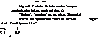
O; = Ki CL/irA; d(Xi/dCL = 20 Щ/А (15)
where 20 as in the “wing” chapter, while K{ = 1 for sufficiently large values of h/b, and K[ = 2 for the limiting case of the foil planing at the surface. This function is plotted in figure 9.
|
WATER
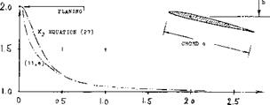
SUBMERGENCE НлТІО h/c Figure 10. Factor K2 (equation 27) indicating the increment of the two-dimensional angle of attack required for a submerged hydrofoil, to obtain a certain lift coefficient; equation (18). |
(10 Technical reports on hydrofoils and hydrofoil boats. A selection listed in (11) (14) (15). More than ЗСЮ sources (possibly half of them available to the public), between 1947 and 1961, are listed in “Bibliography and Literature Search” by Tech Info Center, North American Aviation Rpt S&ID 1961-157; AD-282,464.
(11) Analysis of data on submerged hydrofoils :
a) Wu, Finite Span, J Math к Phys 1954 p 207.
b) Breslin, Ship Theory for Hydrofoils, J. Ship Research Apr 1957, Mar 1960, Sept 1961.
c) Wadlin, Calculation, NACA TN 4168, NASA R-14.
d) Wadlin, Theor and Experiment, NACA Rpt 1232.
e) Schuster, Oscillating Foils, (1960); AD-257,305.
(12) Lifting characteristics of biplane wings:
a) Kuhn, Distribution Betw Panels, NACA Rpt 445.
b) Diehl, Relative Loading, NACA Rpt 458 (1932;.
CIRCULATION. When approaching the free surface of the water, the lift of a two-dimensional hydrofoil reduces also. As pointed out in (ll, e) the upper side of the foil loses lift, while the lower side remains unaffected by the proximity of the water surface. At or “in” the surface (planing) the circulation is reduced to half, for a given angle of attack. There are two analytical approaches to this effect:
a) We will replace the upper panel of the imaginary biplane by a lifting line, tentatively with the same circulation as in the lower panel:
Г — 0.5 CL Vc = w2rir (16)
This means that at the radius r = 2 h, there will be the circulation velocity
w/V=(CL/8ir)/(h/c) (17)
This velocity w is a component directed against the oncoming V. This consideration leads to an increment of the angle of attack corresponding to
A(do</dC^) = (dcx/dC^) (c/h)/4ir = 0.08(dcx/dCL)/(h/c)
where do^/dC^ = uncorrected biplane “lift angle” (equation 30). The formulation does no longer hold, say below h/c = 0.4; it does agree, however, with the more complete analysis in (12).
b) According to (ll, c) we have in two-dimensional flow, the factor
K2 = (16(h/c)2 + 2]/[16(h/c)2 + 1] (18)
This equation, also approximating three-dimensional conditions, is plotted in figure 10. The first term of the “lift angle” will then be
dofg/dCL = 1^(10 + 10/A2) (19)
n
where (10/A ) taken from the “wing” chapter, accounts for the influence of the chord (lifting surface). A function for as indicated in (ll, e) is also plotted in figure 10.
Experimental results proving (a) or (b) to be correct, are hard to find. It is suggested, however, to accept equations (18) and (19).
![]()
![]()
![]()
![]()
 “LIFT ANGLE”. Using the induced angle as in equation (20) the “lift angle” of a fully submerged hydrofoil (wing) is expected to be
d<*7dCL = K2[ 10 + (10/A2)] + (K£ 20/A)
Experimental derivatives of hydrofoils are plotted in figure 11. Equation (30) serves well to explain the angles as tested.
DRAG DUE TO LIFT. We see that the “induced” factor is involved in all terms of the lift equations. As stated in (ll, c) this is partly empirical. When it comes to due – to-lift drag, it is necessary, however, to be specific. Regarding the linear component, the biplane concept indicates
Cd1=KLCl/Va (21)
It is suggested, however, to consider the increment of the angle of the lower panel as in equation ( 26) as a drag-increasing component. The non-linear component is a normal force. Its drag component is simply
ACd = ДС^ sino( (22)
SMALL ASPECT RATIOS. Hydrofoils as considered
so far, have higher aspect ratios (say at least A = 3). However, when using hydroskis, very small aspect ratios may also be of interest. Simplifying the formulation as in (11,c) we obtain for the linear term of the lift
dCL/dctf= A 2 ir/3iq « A/30°K[ (23)
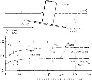
Where K[ is taken from figure 9. Correlation of experimental points in figure 12, is not very good. Replacing the 30 by 360/T2 – 36°, as in the “low aspect ratio” chapter, agreement is found with data from (16,c). The question then remains why lift reported in (16,a) is higher than expected by theory.
|
Figure 12. The lift of flat plates (16,a, c) and of profiled hydroskis (16,d), all having an aspect ratio of 0.25, as a function of their submergence ratio. |
STRUTS are needed to support a hull above 2 or 3 hydrofoils. A larger main foil may have 2 struts, while a smaller control foil is usually connected with the hull by means of one central strut. As explained in chapter VIII of “Fluid-Dynamic Drag”, any disturbance on the upper side of a wing is likely not just to reduce its lift,
but to increase its induced angle and induced drag. Results of wind-tunnel tests (15,e) on the assembly as in figure 13, are as follows:
|
configuration |
dcx°/dCL |
doc.7dCL doC{/dCL |
dCD/dCL |
CL* |
|
|
plain wing alone ————— |
15.4° |
3.9 |
0.068 |
0.077 |
1.05 |
|
wing with nacelle—————- |
00 T |
4.3 |
0.075 |
0.078 |
0.86 |
|
wing-nacelle – strut——– |
15.2° |
3.7 |
0.065 |
0.081 |
1.05 |
|
wing with strut————— |
16.0° |
4.5 |
0.078 |
0.087 |
1.04 |
![]()
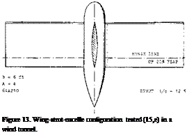 The two-dimensional “lift angle” is assumed to be 11.5°, for A = 4. There is no doubt that strut interference reduces the effective aspect ratio by some 10°A The nacelle acts, on the other hand, like a good fairing. Maximum lift (CLx = 1.05) was not affected by the strut.
![]()
![]()
![]()
![]()
![]()
ENDPLATES as described in the “wing” chapter can also be used in connection with hydrofoils. Regarding the factor (figure 9) it is suggested to consider the foil as a lifting line or surface, with the same h/b as without plates, whose circulation and effective aspect ratio are increased. Experimental results (15,d) confirm this procedure, as long as the end plates do not touch the water surface. [72] [73] [74] [75] [76]
END STRUTS. A pair of struts are often used to support a hydrofoil like a beam, that is with the struts located each, say at 1/4 of the span from the lateral edges. In this manner, the struts have some end-plate effect. However, figure 14 does not confirm that dc</dCL would be reduced, or lift increased, in comparison to a single central strut. When placing the struts at the very ends of a rectangular wing, a “boxplane” is obtained rather than the biplane discussed above. Theory indicates that the factor KL’ as in figure 9, reduces from 2, at the surface, to zero for “very” deep submergence ratios. The connection between boxplane and biplane factor is approximately
KbM= K/(l + h/b) (25)
In reality, end struts are bound to disturb the flow at the upper side of the foil, as shown in (15,b), thus increasing induced angle and drag above that as indicated by theory.
1 6-012
WATER SURFACE
7 = 27 ft/зес
|
4o~
|
V.
8-10
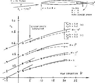
CONTROL FLAPS are needed to balance and to stabilize a hydrofoil craft in roll and pitch. Their characteristics, including hinge moments, are available in the “control” chapter. Figure 15 presents experimental results obtained on the 16-309 section. On account of the comparatively large trailing “wedge” angle of this section, the control effectiveness breaks down at deflection angles beyond + 3 and — 5°, as a consequence of separation from the flap. Regarding control, this type of section (selected on the basis of higher non-cavitating speeds) cannot be considered to be desirable. With the minimum pressure intended to be located at 60% of the chord and a trailing wedge angle of 24°, early separation from the suction side of the flap must be expected. We have indicated in the graph what the lift due to flap deflection would be, if separation did not take place. On the basis of the experimental results presented in the control chapter, the effectiveness ratios dot/d8 = (dC’^/d6)/<dC^/do<) should be as follows:
doc/d<S = 0.8(0.48) = 0.38 Cp/c = 0.2, and Ъ4/Ь = 0.8
dcv/d6 = 0.6(0.60) = 0.36 cf/c = 0.3, and у b = 0.6
dcx:/d<S = average =0.38 as tested (16,a)“l” and “4”
within the range of 6 = — 4° to + 2°. However, outside this range, lift due to deflection is similar to that of split flaps, as indicated in the “flap” chapter. Drag is multiplied, for example tripled for a deflection of 10°. A different foil section and/or a flap shape modified as indicated in the “control” chapter, would certainly give a better performance, in regard to control, lift and drag. In fact, the plain flap in the configuration as in figure 13, provides a dcg/d8 = 0.46, up to some 12° of deflection, on a 64A210 foil section; and that in figure 3, has a do</db = 0.63, that is for a 30°% flap.
|
|
|
Figure 15. Lift of hydrofoil (17,a) produced by deflection of pairs of trailing-edge flaps. |
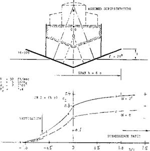
SURFACE-PIERCING hydrofoils are intended to give height (heave), roll and pitching stability through their shape. In theory, their lift, induced angle, roll stability (metracentric height) and even the pitching characteristics of a tandem pair of such foils, is readily understood and susceptible to analysis. The lift of one such foil with a dihedral angle of 20°, is shown in figure 16, as a function of its submergence (but at constant speed and constant angle of attack). Referred to the geometrical total projected planform area, the coefficient reduces, as the foil emerges from the water. These towing-tank tests are performed in perfectly calm water and in steady forward motion. In reality, surface-piercing foils are very problematic because of ventilation irregularly creeping and/or breaking in, from the surface-piercing ends, particularly in sea waves. In the configuration as in figure 16, the struts serve as “fences”. It is reported that at h/b = — 0.1, “a more or less sudden breakdown of the flow over the upper surface occurs”. This emergence ratio corresponds to the condition where the strut junctures are just out of the water. The average variation of lift with submergence (between h/b = 0, and — 0.1) corresponds to dC^/d(h/b) = —2. With this approximate derivative, all stability characteristics and motions of a craft can be estimated. The metacentric height is indicated in the illustration as the difference between point M and the CG. The apparently high roll stability also means that riding in sea waves will be rough.
Figure 16. Lift of a surface-piercing hydrofoil-strut configuration (18,a) as a function of its submergence.
 THE “LIFT ANGLE” of surface-piercing fully-wetted dihedral hydrofoils as derived from (18,c) and from the formulations in this chapter and in the “wing” chapter, is expected to be
dcx°/dCL = (10 Kj/cosf) + (10 K2/A2 cos/™ ) + (Kl 20/A)
Span, area and aspect ratio are based upon projected “wetted” dimensions. For the angle of the section (lifting surface) analysis as in (18,e) indicates a
K2 = 2(1-/775) (26)
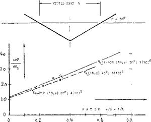
where the angle of dihedral is in degrees. Adopting the average submergence (at 1/2 halfspan) as “the” submergence, it may be said that the equivalent of a “V” foil is a boxplane (figure 9) with a span equal to the distance between the surface-piercing points. Experimental results are plotted in figure 17 as a function of the projected wetted aspect ratio, that is of the ratio c/b = 1/A. The experimental points can be matched by equation (37) when reducing the aspect ratio by
ДА = Ah/c = 2 (Дїі/с)ЛапГ = — 0.2/tan/" (27)
This means that for Г = 30°, the effective aspect ratio is A^= A — (1/3). In other words, the surface-piercing foil ends are not effective for a submergence Ah == 0.1 c, because of surface effects (disturbance and ventilation around the piercing points).
|
Figure 17. Lift angle of surface-piercing hydrofoils as a function of their wetted aspect ratio. |
(18) Characteristics of surface-piercing hydrofoils:
a) Benson, With Struts, NACA W’Rpt L-758 (1742).
b) Sherman, Various Foil Sections, DTMB Rpt C-813.
c) Purser, “V” Tail Analysis, NACA Rpt 823 (3945).
d) Sottorf, In Hamburg T’Tank, ZWB FB 1319 (1940).
e) Bernicker, Flaps, Davidson Lab Rpt 964; AD-601,578


