Correction for Self-Illumination
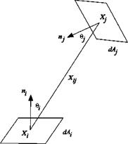
The self-illumination of PSP and TSP results from the luminescent contribution to a point on a surface from all visible neighboring points; it becomes appreciable near a conjuncture of two surfaces and on a concave surface (Ruyten 1997a, 1997b, 2001a; Ruyten and Fisher 2001; Le Sant 2001b). Although the selfillumination can be to certain extent suppressed by taking a ratio between a wind – on image and a wind-off image, it cannot be eliminated without considering an exchange of the radiative energy between neighboring surfaces, which may produce an error in data reduction of PSP and TSP. Therefore, we need to know how much the radiative energy leaves from an area element and travels toward another element. The geometric relations for this inter-surface process are known as view factors, configuration factors, shape factors, or angle factors (Modest 1993). We consider diffuse surfaces that absorb and emit diffusely, and also reflect the radiative energy diffusely. The view factor dFdA,_dAj between two
infinitesimal surface elements dAt and dAj, as shown in Fig. 5.8, is defined as a ratio between the diffuse energy leaving dAt directly toward and intercepted by dAJ and the total diffuse energy leaving dAt, which is expressed as
where n; (or nj) is the unit normal vector of dAt (or dA,), X y is the position
vector directing from dAt toward dA,, and в (or в,) is the angle between the
position vector Xy and the normal nt (or nj). The view factors leaving dAt
directly toward the total surface A, or leaving A, toward dAt, or leaving A,
toward At can be similarly defined by integrating dFAi _Aj (Modest 1993). The
law of reciprocity dAidFd^_ dA, dFc^jis valid for these view factors. The
view factor is a function of the geometric parameters. Methods for evaluating the view factors were discussed by Modest (1993) and a large collection of the view factors for simple geometric configurations was complied by Howell (1982). For partially specular surfaces, the determination of the view factors is more complicated since the bidirectional reflectance distribution function (BRDF) of the paint must be known (Nicodemus et al. 1977; Asmail 1991).
|
The self-illumination correction is applied to an image intensity (or brightness intensity) field denoted by I in this sub-section after it is mapped onto a model surface grid in the object space. Because the image intensity is proportional to the luminescent energy flow rate, the image intensity It at an area element dAt is a
sum of the local intrinsic intensity I{0> and an integration of the contributions from all the neighboring elements, i. e.,
where p’lP2 is the reflectivity of the wall-paint interface at the luminescent
wavelength. In simulations, given a set of the intrinsic intensities I�>, the image intensity It affected by the self-illumination can be obtained using a simple iteration scheme
The more efficient Gauss-Seidel iteration scheme was used by Ruyten and Fisher (2001). In measurements, since the image intensity It is known in PSP and TSP images, an explicit relation is used to correct the self-illumination and recover the intrinsic intensity I�>, i. e.,
The steps for correcting the self-illumination are: (1) measuring the reflectivity p’W ; (2) defining a surface grid consisting of N surface elements dAt; (3)
evaluating the view factors dFdA._dA,; (4) mapping the image intensity It onto the
 |
surface grid; (5) calculating the intrinsic (corrected) intensity I(0> using Eq. (5.16); and (6) calculating a ratio of the intrinsic (self-illumination-corrected) intensities and converting it to pressure or temperature. Ruyten and Fisher (2001) conducted a numerical simulation of correcting the self-illumination for a PSP test of the Alpha jet and found that the error associated with the self-illumination in PSP measurements could reach several percents of actual pressure.
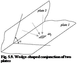
Here, we consider a simple but representative geometric configuration, a wedge-shaped conjunction of two infinitely large plates, as shown in Fig. 5.9; this case allows an analytical estimate of the error induced by the self-illumination. The image intensity at a location on the plate 1 is
Assuming that the image intensity at the plate 2 is homogenous, by integrating the view factor for this configuration (Modest 1993), we obtain the image intensity at the plate1 affected by the plate 2
11 « IT + e,12, (5.18)
where the parameter e, = pY2 (1 + cos a >/2 represents the combined effect of the
angle a between the plates and reflectivity. Clearly, the self-illumination decreases from the maximum value at a = 0o to zero at a = 180o. A reciprocal relation gives the image intensity at the plate 2
I2 – Ґ20> +8,1,. (5.19)
When the parameter є, is small, the image intensity ratio at the plate 1 is
Iiref/Ii – (IZ/I^HI + є, є2 >. (5.20)
The parameter є2 = I(20rf /1^ -1(20) /1(,0> reflects the difference of the relative
influence of the plate 2 on the pate 1 between the wind-off reference and wind-on conditions. Using the Stern-Volmer relation for PSP, we obtain an estimate for the pressure error associated with the self-illumination for the wedge configuration
where A and B are the Stern-Volmer coefficients, and p(0) and p(°f> are,
respectively, the intrinsic PSP-derived pressures in the wind-on and wind-off reference conditions that are not affected by the self-illumination. Similarly, using the Arrhenius relation for TSP, we have an estimate for the temperature error associated with the self-illumination for the wedge configuration
where R is the universal gas constant, Enr is the activity energy of TSP, and
T(0) is the intrinsic TSP-derived temperature that is not affected by the selfillumination.
The above discussion is based on an assumption that the luminescent paint surface is a diffuse surface or Lambertian surface. Nevertheless, a real paint surface is neither Lambertian nor specular. To characterize reflection on a general surface, the bidirectional reflectance distribution function (BRDF) was introduced by Nicodemus et al. (1977). As shown in Fig. 5.10, the incident radiance is generally a function of the incident direction defined by the incident polar angle and azimuthal angle (ві, фі), i. e.,
Lt = Ц(в, ф). (5.23)
The reflection radiance Lr( ві, фі;вг, фг) is quantitatively characterized by the BRDF
Ыв^в’.ф,) = дЬг(в1,ф1;вг, фг)/дЕ1(в1,ф1). (5.24)
where (вг, фг) defines the direction of reflection and the infinitesimal incident irradiance dEt(ві, фі ) over a solid angle element dty is
dEt(ві, фі) = Lt(ві, фі )cos6idmi. (5.25)
The BRDF has a unit of steradian1. Here, the conventional radiometric notations L and E are used for radiance and irradiance, which are also applicable to the luminescent emission.
The BRDF depends on a surface roughness distribution. For a perfectly diffuse surface where the reflection radiance is isotropic, i. e., Lr = const., the BRDF is fr = 1/n (Horn and Sjoberg 1979). For a general surface, the BRDF can be derived based on either the wave equation for electromagnetic waves or geometrical optics models (Beckmann and Spizzichino 1963; Torrance and Sparrow 1967; Nayar et al. 1991). Asmail (1991) gave a bibliographical review on the BRDF. From a viewpoint of application, empirical expressions for the scattered radiance from a rough surface are very useful due to their simplicity (Cook and Torrance 1981; Haussecker 1999). An empirical model for a single light source is
Lr( X) = paEa( X ) + pd E, s (X)(NTLS) + Ps E s (X )p( RTV), (5.26)
where the first, second and third terms are, respectively, the contributions from the ambient reflection, diffuse reflection, and specular reflection. In Eq. (5.26), Pa, Pd, and Ps, are the empirical reflection coefficients for the ambient reflection, diffuse reflection, and specular reflection. As shown in Fig. 5.10, the vectors N, Ls, R, and V are, respectively, the unit normal vector of a surface, the unit vector directing the light source from the surface, the unit main directional vector of the specular reflection, and the unit viewing vector. Ea( X ) and E s( X ) are the irradiances for the ambient environment and light sources, respectively. The function p( RTV) is the directional distribution of the specular reflection, describing the spreading of scattered light. Phong (1975) gave a power function p( RTV ) = ( RTV )n. In general, the main directional vector of the specular reflection, R, is a function of the incident direction of light – Ls. Although there are certain theories for predicting the specular direction R (Torrance and Sparrow 1967), R is not known for a general surface. The unknowns in Eq. (5.26), such as R, the reflection coefficients, and the parameters in p( RTV), have to be determined experimentally by calibration.
Le Sant (2001b) measured the BRDF for the B1 PSP paint with talc using a BRDF calibration rig. As illustrated in Fig. 5.11, the BRDF calibration rig included a lamp for illumination and a spectrometer to measure the reflected light from a sample. The lamp emitted white light, enabling the calibration of the BRDF in the visible range; the lamp moved from 0o at the vertical position to 60o. The zenith (or polar) angle of the spectrometer moved from 0o to 60o and the azimuth angle moved from 0o to 180°, where 180° was in the opposite direction of the emission. Figure 5.12 shows the measured BRDF for the B1 paint, which was nearly Lambertian when the zenith (or polar) angle of illumination was 10°, while specular reflection occurred when the zenith angle increased further. The
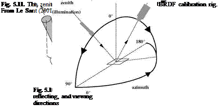 |
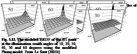
maximum value was always achieved in the specular direction. The low value obtained at the azimuth angle of 0° was incorrect since the spectrometer was in the front of the lamp and thus the PSP sample was no longer illuminated. The measured BRDF showed a superposition of diffuse reflection and specular reflection. A specular peak was observed at the zenith angle of 60° as well as a secondary peak at the azimuth angle of 90°. The value of the diffuse reflection factor depended on the zenith angle of illumination. Le Sant (2001b) was able achieve a good fit to the measured BRDF using the modified Phong model (Phong 1975), as shown in Fig. 5.13, and the modeled BRDF captured the main features of the measured BRDF except the secondary specular peaks.
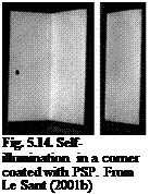
Le Sant (2001b) also studied the self-illumination in a corner to validate a correction algorithm. The corner was painted with a Pyrene-based paint providing an image significantly affected by the self-illumination near the junction of the two plates, as shown in Fig. 5.14. Then, the left plate was covered with a black sheet, removing the effect of the self-illumination on the right plate, as shown in
 |
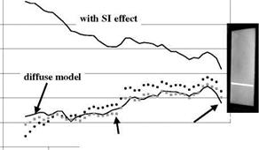
the right image in Fig. 5.14. Figure 5.15 shows results before and after correcting the self-illumination based on the diffuse surface model and the Phong model. The self-illumination correction was effective; the self-illumination effect was reduced to 15% from about 40% near the junction. This paint behaved mostly like a diffuse paint such that the Phong model did not exhibit a significant improvement. Although the Phong model might improve the accuracy of correction for a surface with strong specular reflection, the computation time for the Phong model was much longer than that for the diffuse surface model.
![]()
![]()

![]()
![]()
 Phong model
10 20 30


