General Simplifications Effect of the Element Offset
To reproduce the outer mold surface of the real wing structure the shell elements forming the wing skin must have an offset relative to the nodes of the discretized geometry. By neglecting the element offset the distance of skin panels relative to the neutral axis of the wing box will be overestimated. This effect will increase the moment of inertia of the wing box cross-section following the parallel axis theorem, which in turn results in higher bending stiffness of the wing structure compared to the exact solution. The torsional stiffness will also be affected by the increasing distance between the mid-lines of the top and bottom covers in accordance with the Bredt-Batho formulation. The same effect on the bending stiffness appears by ignoring the offset distance of beam or rod elements representing the stiffening structural members. The latter case will be considered separately for each stiffening component.
To estimate the impact of the modeling simplifications on the deformation behavior of the wing box the structural response is calculated for the idealized and the reference structural models. The integral values of the deviation in bending angle, torsion and resulting elastic angle of attack compared to the reference structure are given in table 3. For the FE wing model without element offset within the top and bottom covers the bending stiffness increases accordingly to the a. m. effects resulting in an approximately 4% smaller bending angle which in turn reduces the local angle of attack (cp. section 1.2). Torsion deformation is also reduced by 1.7% due to the higher torsional stiffness having an opposite effect. The change in both degrees of freedom results in 4.1% smaller elastic angle of attack due to the dominant influence of the bending stiffness (compare the values [Aw’]tr and [AQ]tr in table 3). The sign of the transformed deviation parameter [AQ]tr changes due to the relation to the maximum value of elastic angle of attack a^.
The converged angle of attack calculated for the more simplified structure shows a 0.9% smaller value compared to the reference model (see fig. 5). This result corresponds with the trend predicted by the negative change of the elastic angle of attack [Aael} given in table 3. Smaller (negative) values of ael (y) along the span have a reduced effect on the load distribution compared to the reference structure and, therefore, the target lift can be achieved under smaller angle of attack.
Table 3 Deviations of bending angle, torsional angle and elastic angle of attack for different states of modeling simplification
|
shell elems. without offset |
simplified BCs |
|||
|
rel. glob, deviation |
rel. glob, deviation: transf. |
rel. glob, deviation |
rel. glob. deviation: transf. |
|
|
[Aw’]/[Aw’]tr/% [AQl[AQ]trl% [Aae,}/% |
-3.955 -1.699 |
-4.327 0.228 -4.101 |
-5.446 -29.534 |
-5.782 3.974 -1.806 |
|
Simplified Boundary Conditions |
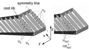
At the root, the wing is mounted to the wing center box and to the main frames of the fuselage. Despite of high local wing box stiffness, a minimal translational displacement of the wing skin in span wise direction is possible in the root area. If this infinitesimal displacement is constrained by restriction of all translational and rotational degrees of freedom along a root rib curve (see fig. 3, on the right hand side), a reduction of bending and torsion deformations due to the overestimation of wing root rigidity can appear. This kind of idealization is used when the structure of a half wing is realized without the center box. To assure realistic boundary conditions, see figure 3 on the left hand side, the displacement of upper and lower edges of the root rib, should be constrained only in direction normal to the skin surface (z-direction). The nodal displacements in spanwise direction (along the y-axis) as well as nodal rotations have to be constrained only at the symmetry plane of wing center box.
The effect of higher wing root rigidity has a local character influencing the bending and torsional deformations in the form of additional (negative) rigid body motions, resulting in the integral deviation of 5.4% within the bending and approx.
|
Fig. 3 Realistic and simplified boundary conditions |
30% within the torsional angle. Due to the mutually directed influencing tendencies of these deformations, the resulting change within the elastic angle of attack is only 1.8% (see table 3). From the transformed values and [AQ}tr in table 3 it can
be seen that the rather high contribution of bending deviation in flight direction is compensated by the much higher change of the torsional angle.
The results of the coupled aeroelastic analysis confirms with the tendency of the deviation of elastic angle of attack ael (y) obtained by the structural response. This moderate tendency of the change of is reflected in the deviation of the equilibrium state angle of attack AaEqSt /aEqSt being only 0.54% (see fig. 5).


