LIFT-CAVITATION-VENTILATION
The basic principles of cavitation are given in Chapter I and in “Fluid-Dynamic Drag”. As the speed is increased, cavitation will be encountered and the lift of the foil will be reduced. Thus, lift will be obtained on an airfoil in spite of cavitation. At speeds lower than cavitation would be expected, it can be shown that with proper ventilation a finite cavitation number can be simulated.
Incipient Cavitation. The critical cavitation number is that where at a particular point on the surface of a body or wing the local static pressure reduces to that of vaporization. This means that
Pnnin~ Pv “TCpmm + Pa – p^ =0 (42)
or:
c pmin = – (Pa – Pv ) q = – cra « – 195/(V, m/s) (43)
Vice versa, the incipient cavitation number is
A –Cpmin « 195/(V, m/s) and the critical speed is
Vcnt = /і95/сґа in (m/s) Vcrjt ~ 26//o7J in knots
Minimum Pressure. The minimum pressure coefficients are known for body shapes such as foil sections in particular, and thus the critical speed where cavitation can be expected can be found in equations 44 and 45. In “Fluid-Dynamic Drag”, CPrT!!n for zero lift, as well as for optimum camber, are given as a function of the lift coefficient. Both of these functions are quoted in the “compressibility” chapter.
Cpmin =-2.1 (t/2x)@CL=0 (46)
where x = location of the maximum thickness (for example at 40% of the chord). Also for properly cambered sections:
^ Cpmin – К CLOpt (47)
where К between 0.75 (for thickness locations near 30% of the chord) and 0.85 (for locations around 50% of the chord). Adding the two components the minimum
pressure at the upper side of foil sections or hydrofoils is obtained at and around their design lift coefficient. As an example, the 4412 section is shown in figure 25, both tested for pressure distribution in a wind tunnel (29,a) and for incipient cavitation in a water tunnel (30,d). At lift coefficients, at least between 0.2 and 0.6, complete agreement is found. This means that cavitation readily starts when the minimum pressure reduces to the level of the vapor pressure. In a water tunnel cavitation is achieved either by increasing the speed (the q in Cpmm) or by reducing the pressure within the tunnel as a whole (the p in <r). " 3
Pressure Peaks. There is a mathematical relationship not only between the minimum pressure coefficient of any foil section, but also between the critical Mach number (in air) and the critical cavitation number and/or the critical speed (in water). Both these critical speeds can be exceeded, however, without any loss of lift, when the minimum pressure appears only in a more or less narrow peak. Since the reasons and extent of these transgressions are different, it is not possible in the presence of peaks to make correct predictions in regard to cavitation, neither on a theoretical basis nor from experimental evidence in air. As shown in “Fluid-Dynamic Drag” the delay as found around the leading edges of foil sections seems to correspond to
= – 0.08 Cpmin (48)
An example is shown in figure 26. Within a “bucket” similar to that as found in laminar-type airfoil sections, the cavitation number (indicating the onset of cavitation) agrees with the minimum pressure coefficient found as the sum of equations 46 and 47. Outside the bucket the cavitation number increases at a rather high rate. This means that cavitation starts at a much lower speed. If, for example, Of = 2 (at the upper side of a foil section, at CL = 0.9) instead of of = 0.5 (at CL around 0.4) then the critical speed in open water will be reduced in accordance with equation 45 roughly from 40 to /0.5/2 40 = 20 knots.
![]()
Pressure distribution test
(a) On 4412 Section, NACA TR 563 1936.
|


![]()
![]()
![]()


![]()
![]()
![]()
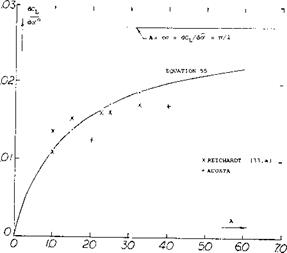
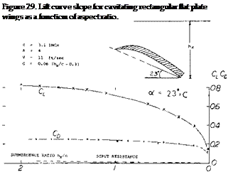
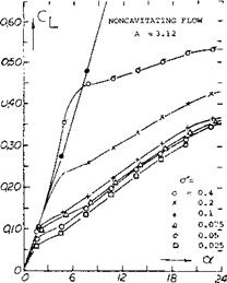
Cavitation Number Fffect. At cavitation numbers above zero it was shown (32,e) that the normal force coefficient is increased by aCn = cr. Evaluation of the data of (33,a) indicates that
CL = .8 cr (56)
Based on this analysis it would appear as in the case of small aspect ratio wing, Chapter XVII, that the flow about the edges is of importance.
Supercavitation. Since cavitation is no longer avoidable in conventional foil sections at the higher speeds, the idea was conceived to accept cavitation at the upper side and to make the best of it by forming the lower side properly. Figure 30 presents one such supercavitation section. Increased drag, a shortcoming of such sections is the fact that in a hydrofoil boat, for example, the flow pattern has necessarily to go through a transition from fully attached or fully separated to fully cavitated. Another disadvantage is found in the fact that drag can take place within certain boundaries of the lift coefficient. Even in marine propellers where cavitation is a well-known plaque, no supercavitating designs seem to be in practical operation some ten years after their invention.
1.0
OB
06
. /
102
/
/ ^
(32) Supercavitating Hydrofoils Theory:
(a) Acosta, Three-Dimensional Supercavitating Hydrofoils, Ca. Inst of Technology to ONR 1974.
(b) Nishujama, Theory Hydrofoils Finite Span, ZAMM Vol 50, 1970.
(c) Acosta, Hydrofoils and Hydrofoil Craft Annual Review Fluid Mechanics, Vol 5 1973.
(d) Hough, J. Ship Res. 13:53-60 (1969)
(e) Betz, Influence of Cavitation Upon Ship Propellers, Proc. 3rd International Congress, Mechanics Stockholm 1930 Vol. 1 page 411.
(33) Finite Hydrofoil Wings
(a) Reichardt, Rectangular Wings with Cavitation, Max – Planck-Institute for Stomungsforscheing Gutlingen 1967.


