Mathematical Approach
The shape and behavior of the Joukowski airfoil are determined by applying an exact mathematical method. The analysis uses the theory of complex variables— in particular, conformal mapping—to map (i. e., transform) a right-circular-cylinder shape (for which the flow with circulation already was determined) in one complex plane into an airfoil shape in a second complex plane. Conformal mapping means that intersecting lines are mapped such that the angles between the lines in the two planes are preserved. To accomplish this mapping, the Joukowski transformation uses a simple transformation function—namely, the first two terms of an infinite series that is the most general transformation formula. This simplicity leads to constraints on the resulting airfoil geometry.
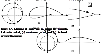
If it is to look like an airfoil, the shape resulting from the transformation must have a rounded leading edge and a sharp trailing edge. To generate a sharp trailing edge by means of the transformation, the circular cylinder (i. e., a circle in the cylinder plane) must pass through one of the critical points of the trans – formation—that is, through a point where the transformation is not conformal. This critical point is located on the x-axis in the circle plane and the center of the cylinder is offset from the origin, being located in the second quadrant of the plane. Figure 5.4 illustrates the geometry of the mapping for several cases of interest. The distance that the center of the circle lies above the x-axis determines the thickness ratio of the airfoil, whereas the distance it lies to the left of the y-axis determines the magnitude of the camber ratio. The cylinder radius is simply a scale factor.
The z (i. e., cylinder) plane is a complex plane in which the cylinder appears as a circle in cross section and a point on the plane is given by the complex variable z = x + iy. Similarly, a point in the q (i. e., circle) plane is described by q = £ + ip. The Joukowski transformation is given by q = z + C2/z = qi + q2, where C is a constant.
Referring to the z (i. e., cylinder) plane in Fig. 5.4, the first term of the Joukowski transformation (qi = z) maps a point-by-point reproduction of the cylinder in the z plane into a “major” circle in the q (i. e., circle) plane. The second term (q2 = C2/z) maps the cylinder in the z-plane into a second (“minor”) circle shown as a dashed line in the circle (q) plane. However, compared to the major circle, the minor circle has a reduced radius, the center of the circle is transformed across the imaginary (i. e., vertical) axis, and a point on the major circle described by the polar angle 0 is reflected in the real (i. e., horizontal) axis as (-0).
 |
Finally, the complete transformation of the cylinder into the qJ (i. e., airfoil) plane is accomplished by the vector addition of two complex quantities, qJ = q1 + q2. One point, z, on the cylinder and its image on the major and minor circles and then on the airfoil surface is illustrated in Fig. 5.4. A complete illustration is found in Program JOUK.
 |
With the geometry established, a function of a complex variable that relates the velocity components on the airfoil to the velocity components on a cylinder at corresponding mapping points can be determined and then transformed. Because the flow field around a cylinder is known, the velocity (and, hence, the static pressure) on the airfoil can be found at corresponding points. If only the lift is required, finding the circulation around the airfoil provides the answer through the vortex theory of lift.
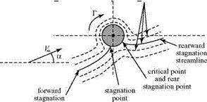
It may be shown that the Joukowski transformation preserves the value of the circulation in the two planes. That is, the circulation around the airfoil is the same as the circulation around the related cylinder, and the lift force on the airfoil follows from the Kutta-Joukowski Theorem once the circulation is known. How is the unique value of the circulation around the cylinder established? Recall that the critical point on the cylinder transforms into the airfoil trailing edge. Now, to satisfy the Kutta condition, the trailing edge of the airfoil must be a stagnation point. This means that the critical point in the circle plane also must be a stagnation point, as shown in Fig. 5.5.
Once the freestream flow direction, a, is selected (which is also the airfoil angle of attack) and the location of the center of the cylinder is chosen, the magnitude of the circulation required to hold the rear stagnation point on the cylinder at the critical point can be calculated. The lift per unit span, L’, on the corresponding Joukowski airfoil follows directly. Inviscid theory predicts that the drag of the Joukowski airfoil is zero in accordance with the D’Alembert’s Paradox discussed previously.
 |
|
Mathematically, this is because the flow is symmetrical about this cylinder relative to a line through the center and perpendicular to the freestream flow direction.
Results
Recall the definition of the two-dimensional lift coefficient:
The result for a symmetrical Joukowski airfoil at moderate angle of attack is:
Ce = 2 n(1 + e)a,
where a is the geometric angle of attack of the airfoil (i. e., the angle between the freestream direction and the airfoil chord line) and e is a small number proportional to the thickness ratio. For a vanishingly thin (e ^ 0) symmetric Joukowski airfoil, the lift curve slope is:
For a 10 percent-thick Joukowski airfoil, the theoretical lift-curve slope is only about 7 percent higher. Remember that these results are exact; they suggest that if an airfoil is thin (i. e., less than 10 percent), then the effect of the thickness ratio on the lift-curve slope can be ignored with minor error. Keep this in mind when the assumptions involved in the thin-airfoil theory are presented herein.
Unfortunately, the Joukowski transformation leads to an airfoil shape that is not practical based on experience. The mean camber line is always a circular arc regardless of which airfoil camber and thickness ratios are chosen, and the maximum thickness of the Joukowski airfoil is always at about the quarter-chord—which, in practice, is too far forward. Finally, the trailing-edge angle is always a cusp (i. e., has a zero-included angle). It is possible to generalize the Joukowski airfoil shape to incorporate a finite trailing-edge angle by taking more terms in the general transformation formula; however, the method becomes complicated even for symmetrical airfoils.
The Joukowski airfoils were used in the 1930s in Europe in several sailplane designs. They formed the basis of the successful Gottingen series of airfoils that are used in the present day in low-speed designs. Preceding World War II, they were considered state-of-the-art for high-performance sailplane applications. Even if the Joukowski airfoil is not currently considered to represent a practical airfoil-design approach, it has a role in modern analysis because the pressure distribution and lift results are based on a rigorous theory with no approximations. The complex variable analysis thus provides useful benchmark results against which to compare numerical or approximate solutions.
Numerical-analysis methods for inviscid flow were developed that are, in a sense, the inverse of the approach described previously. In these methods, an arbitrary airfoil shape is selected (including a finite trailing-edge angle) and then is transformed into a circle. The flow field for the circle (cylinder) is solved and this solution is transformed back to the airfoil plane, yielding the velocity distribution (and, hence, the pressure distribution) on the airfoil. However, numerical-panel methods (discussed herein) are preferred for solving this problem.
Finally, although the conformal-mapping approach and the underlying complex – variable theory now are not used directly in the solution of practical aerodynamics problems, the ideas involved are of interest in the sense described. If students are interested in more details on the application of conformal-mapping methods, they should consult the extensive literature on the subject published previously in the 1930s (cf. Glauert, 1926/1947).


