Methods of varying the tail plane lift
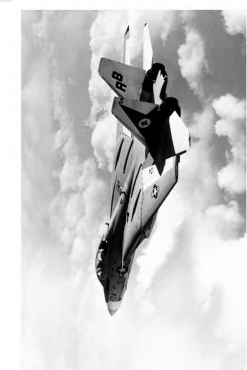
For many years, the most common method of altering the tail plane lift was to provide a hinged rear portion called an elevator. Moving this up or down alters the camber of the surface, and thus changes the lift. However, in supersonic flight, changes of camber do not produce much of a change in lift, and it is better to move the whole tail surface as a single slab. A slab type tail surface may be seen in Figures 5G and 5H (overleaf). The moving slab tailplane is nowadays sometimes used even on low-speed aircraft as there are structural and manufacturing advantages to this type of tail. On some aircraft, particularly large transports, the two approaches may be combined. The whole tailplane can be moved, mainly to provide for trimming, and a hinged elevator is also used, mainly for control and manoeuvre.
Conditions of balance considered numerically
We have so far avoided any numerical consideration of the forces which balance the aeroplane in straight and level flight; in simple cases, however, these present no difficulty.
When there is no load on the tail plane the conditions of balance are these –
1. Tift = Weight, i. e. L = W.
2. Thrust = Drag, i. e. T = D.
3. The ‘nose-down’ pitching moment of L and W must balance the ‘tail – down’ pitching moment of T and D.
|
|
|

|
|
The two forces, L and W, are two equal and opposite parallel forces, i. e. a couple; their moment is measured by ‘one of the forces multiplied by the perpendicular distance between them’. So, if the distance between L and W is x metres, the moment is Lx or Wx newton-metres.
Similarly, T and D form a couple and, if the distance between them is у metres, their moment is Ту or Dy newton-metres.
Therefore the third condition is that –
Lx (or Wx) = Ту (or Dy)
To take a numerical example: Suppose the mass of an aeroplane is 2000 kg. The weight will be roughly 20 000 N. T = W. So T = 20 000 N.
Now, what will be the value of the thrust and drag? The reader must beware of falling into the ridiculous idea, which is so common among students, that the thrust will be equal to the weight! The statement is sometimes made that the ‘Four forces acting on the aeroplane are equal’, but nothing could be farther from the truth. L = W and T = D, but these equations certainly do not make T = W. This point is emphasised for the simple reason that out of over a thousand students to whom the author has put the question, ‘How do the think the thrust required to pull the aeroplane along in normal flight compares with the weight?’ more than 50 per cent have suggested that the thrust must obviously equal the weight and over half the remainder have insisted that, on the other hand, the thrust must be many times greater than the weight! Such answers show that the student has not really grasped the fundamental principles of flight, for is not our object to obtain the maximum of lift with the minimum of drag, or, what amounts to much the same thing, to lift as much weight as possible with the least possible engine power? Have we not seen that the wings can produce, at their most efficient angle, a lift of 20, 25 or even more times as great as their drag?
It is true that there is a great deal of difference between an aeroplane and a wing; for whereas a wing provides us with a large amount of lift and a very much smaller amount of drag, all the other parts help to increase the drag and provide no lift in return. Actually it is not quite true to say that the wings provide all the lift, for by clever design even such parts as the fuselage may be persuaded to help. Efforts to increase the lift may be well worth while, but even total increase of lift from such sources will be small, whereas the addition of the parasite drag of fuselage, tail and undercarriage will form a large item; in old designs it might be as much, or even more than the drag of the wings, but in modern aircraft with ‘clean’ lines the proportion of parasite drag has
Fig 5H Slab tail planes (opposite)
(By courtesy of the Grumman Corporation)
Large slab tail planes and twin fins are evident on this photograph of the F-14.
been much reduced. None the less it may result in the reduction of the lift/drag ratio of the aeroplane, as distinct from the aerofoil, down to say 10, 12 or 15.
So it will be obvious that the ideal aeroplane must be one in which there is no parasite drag, i. e. in the nature of a ‘flying wing’; we should then obtain a lift some forty times the drag. At present we are a long way off this ideal except for high-performance gliders.
In our numerical example, let us assume that the lift is ten times the total drag, this being a reasonable figure for an average aeroplane. Then the drag will be 2000 N; so thrust will also be 2000 N. This means that an aeroplane of weight 20 000 N can be lifted by a thrust of 2000 N; but the lift is not direct, the work is all being done in a forward direction – not upwards. The aeroplane is in no sense a helicopter in which the thrust is vertical, and in which the thrust must indeed be at least equal to the weight.
To return to the problem –
L = W = 20 000 N
T = D = 2000 N (This is merely an approximation for a good type of aeroplane)
Lx = Ту
So 20 000 x = 2000 у
So if T and D are 1 metre apart, L and W must be 1/10 metre apart, i. e. 100 mm. In other words, the lines of thrust and drag must be farther apart than the lines of lift and weight in the same proportion as the lift is greater than the drag (Fig. 5.7).
L = 20 000 N
D = 2000 N
у metres
T= 2000 N
W= 20 000 N
![]() Balance of forces – no load on tail
Balance of forces – no load on tail


