Modern Front Stage Compressor
As an example of the method applied to a realistic geometry, consider the case of the front stage of a modern compressor. This three-dimensional con-
|
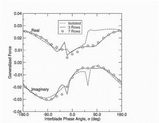
Figure 6. Comparison of Generalized Force for different number of blade rows |
|
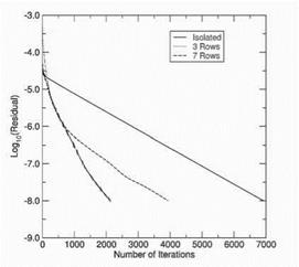
Figure 7. Convergence history for multistage calculations with various number of blade rows |
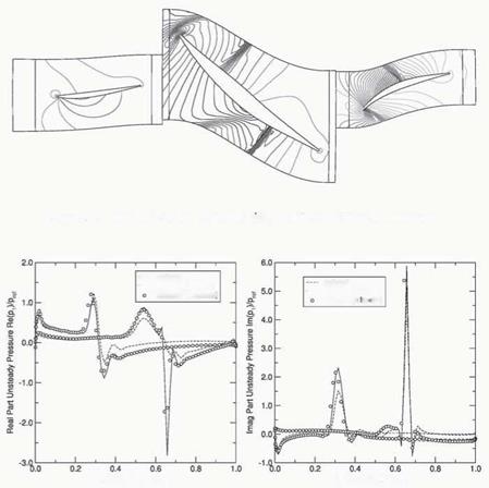
figuration consists of three blade rows (IGV/rotor/stator). Figure 8 shows the static pressure distribution near the midspan location computed using a steady Euler multistage ft>w solver. Note, that the contours at the inter-row boundaries are not continuous since the only the circumferential averages of the flows in each blade row match at the boundaries.
Next, the middle blade row (rotor) is assumed to vibrate in its first bending mode and frequency. Figure 9 shows the real and the imaginary parts of the unsteady pressure on the rotor row for an interblade phase angle of -30. deg. The multistage solution was computed using one and eight spinning modes in
 Figure 8. Pressure contours at the midspan ot a front stage compressor
 Surface Location, x/c
Figure 9. Unsteady pressure distribution on the surface of rotor blades vibrating in first bending with a = -30 o the coupling procedure. One can see that there is significant difference between the isolated and coupled (multistage) computations.
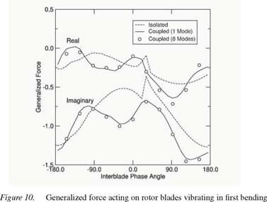
The unsteady pressure distribution can be integrated to obtain the unsteady modal force acting on the rotor blades due to their vibration. Figure 10 shows the real and imaginary parts of the computed generalized forces on the rotor blades as a function of interblade phase angle. Note the significant difference between the forces computed using a single blade row (the rotor) and three blade rows (the rotor and the upstream IGV and downstream stator). Clearly, multistage effects are important. However, the generalized force computed using just one spinning mode is in very good agreement with the force computed using eight spinning modes, indicating the dominant coupling is in the fundamental mode.
|
|
These results, and earlier two-dimensional results produced by Silkowski and Hall, 1998, Hall and Silkowski, 1997, Silkowski, 1996, confirm that the aerodynamic damping of a blade row that is part of a multistage machine can be significantly different than that predicted using an isolated blade row model. This is an important result since most unsteady aerodynamic theories currently used in industry assume that the blade row can be modeled as isolated in an infinitely long duct. However, a good estimate of the aerodynamic damping can be obtained using just a few spinning modes in the model. In fact, most of the unsteady aerodynamic coupling between blade rows occurs in the fundamental spinning mode, that is, the spinning mode associated with the original disturbance. Scattered modes are relatively less important.
4. Conclusions
In this paper, we have presented a new technique for computing unsteady fbws in turbomachinery. The method, which is particularly well suited for the computation of the aerodynamic forces the produce flutter and forced response in turbomachinery, is computationally very efficient, requiring the same order of magnitude of CPU time as a comparable steady ft>w calculation. In addition, we have shown by numerical example that multistage infhences can be quite pronounced. The authors’ recommendation is that multistage effects be modeled in all unsteady aerodynamic calculations associated with flutter and forced response. Finally, we note that the predominant coupled among blade rows in a multistage machine is through a single spinning mode (the fundamental mode), and it appears that only the nearest two neighboring blade rows have a significant inflience on an embedded blade row.
Acknowledgments
This work was supported in part through a grant from NASA Glenn Research Center (NAG3-2627). The authors would also like to thank Professor Namba for providing numerical results from his multistage analysis, to which we compared our results, and which appear in this article.
References
Buffum, D. H. (1993). Blade row interaction effects on flitter and forced response. AIAA Paper 93-2084.
Hall, K. C. and Clark, W. S. (1993). Linearized euler prediction of unsteady aerodynamic loads in cascades. AIAA Journal, 31(3):540-550.
Hall, Kenneth C. and Silkowski, Peter D. (1997). The inflience of neighboring blade rows on the unsteady aerodynamic response of cascades. Journal of Turbomachinery, 119(1):83-95. Namba, M, Yamasaki, N, and Nishimura, S (2000). Unsteady aerodynamic force on oscillating blades of contra-rotating annular cascades. Proceedings of the 9th ISUAAAT Conference. Silkowski, P. D. and Hall, K. C. (1998). A coupled mode analysis of unsteady multistage flaws in turbomachinery. Journal of Turbomachinery, 120(3):410-421.
Silkowski, Peter D. (1996). A Coupled Mode Method for Multistage Aeroelastic and Aeroacous – tic Analysis of Turbomachinery. PhD thesis, Duke University, Durham, NC.
Whitehead, D. S. (1987). Classical two-dimensional methods. AGARD Manual on Aeroelasti – city in Axial Flow Turbomachines, Vol. 1, Unsteady Turbomachinery Aerodynamics (AG – 298).
AEROACOUSTICS


