Other integral thickness interpretations
|
9* |
 |
|||
In incompressible flow where p = pe = constant, the displacement, momentum, and kinetic energy thicknesses have additional interpretations in terms of the geometry of the normalized velocity profile U. By setting p/pe = 1, the thickness definitions (4.4),(4.11),(4.12) simplify as follows.
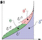
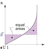
These incompressible thickness definitions can be interpreted as the geometric areas defined by the U, U 2,U3 profiles as shown in Figure 4.4 on the left. The displacement thickness has another interpretation as the height of the line which splits the profile into two equal areas. This is shown in the middle sketch of Figure 4.4.
 |
 |
 |
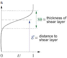
In a separated flow region, such as would occur on the upper rear surface of the nearly-stalled airfoil shown in Figure 3.7, most of the vortical fluid of the boundary layer has lifted off the wall. A typical velocity profile for this type of flow is shown in Figure 4.4 on the right. It is more correct to call this a free shear layer which lies between two distinct flow regions. One is the potential flow region outside the shear layer, and the other is the nearly-stagnant recirculating flow region between the wall and the shear layer. In this case we can interpret 9 as being a measure of the thickness this shear layer (numerically its thickness is approximately 89). In contrast, 5* is a measure of the distance from the wall to the shear layer centerline.
Figure 4.4: Interpretation of the integral thicknesses for incompressible flow, in terms of the geometry of the normalized velocity profile U = u/ue, and also U2 and U3. Since the horizontal scale is dimensionless, the areas have the same length unit as the vertical n axis.


