Our heavyweight helicopter equal in the world does not have
In Rostov started production of the most load-lifting rotary-wing car The Russian holding «Helicopt[...]

Everything about aircrafts and helicopters. News and events in aviation worldwide. Civil, transportation, military helicopters and airplanes.

Everything about aircrafts and helicopters. News and events in aviation worldwide. Civil, transportation, military helicopters and airplanes.

Everything about aircrafts and helicopters. News and events in aviation worldwide. Civil, transportation, military helicopters and airplanes.

Everything about aircrafts and helicopters. News and events in aviation worldwide. Civil, transportation, military helicopters and airplanes.


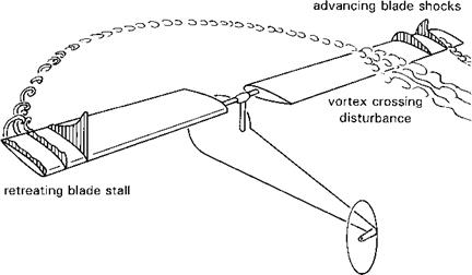
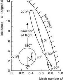
While aeroplanes stall boundaries in level flight occur at low speed, helicopter stall boundaries occur typically at the high-speed end of the OFE. Figure 2.9 shows the aerodynamic mechanisms at work at the boundary. As the helicopter flies faster, forward cyclic is increased to counteract the lateral lift asymmetry due to cyclical dynamic pressure variations. This increases retreating blade incidences and reduces advancing blade incidences (a); at the same time forward flight brings cyclical Mach number (M) variations and the a versus M locus takes the shape sketched in Fig. 2.10. The stall boundary is also drawn, showing how both advancing and retreating blades are close to the limit at high speed. The low-speed, trailing edge-type, high incidence (0(15°)) stall on the retreating blade is usually triggered first, often by the sharp local incidence perturbations induced by the trailing tip vortex from previous blades. Shock- induced boundary layer separation will stall the advancing blade at very low incidence (0(1-2°)). Both retreating and advancing blade stall are initially local, transient effects and self-limiting on account of the decreasing incidence and increasing velocities in the fourth quadrant of the disc and the decreasing Mach number in the second quadrant. The overall effect on rotor lift will not be nearly as dramatic as when an aeroplane stalls at low speed. However, the rotor blade lift stall is usually accompanied by a large change in blade chordwise pitching moment, which in turn induces a strong, potentially more sustained, torsional oscillation and fluctuating stall, increasing vibration levels and inducing strong aircraft pitch and roll motions.
|
Fig. 2.9 Features limiting rotor performance in high-speed flight |
|
Fig. 2.10 Variation of incidence and Mach number encountered by the rotor blade tip in forward flight |
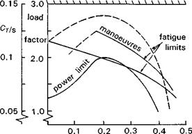
Rotor stall and the attendant increase in loads therefore determine the limits to forward speed for helicopters. This and other effects can be illustrated on a plot of rotor lift (or thrust T) limits against forward speed V. It is more general to normalize these quantities as thrust coefficient Ct and advance ratio д, where
^ T V
Ct = p(OR)2nR2 ’ Д = OR
where O is the rotorspeed, R the rotor radius and p the air density. Figure 2.11 shows how the thrust limits vary with advance ratio and includes the sustained or power limit boundary, the retreating and advancing blade lines, the maximum thrust line and the structural boundary. The parameter s is the solidity defined as the ratio of blade area to disc area. The retreating and advancing blade thrust lines in the figure correspond to both level and manoeuvring flight. At a given speed, the thrust coefficient can be increased in level flight, by increasing weight or height flown or by increasing the load factor in a manoeuvre. The manoeuvre can be sustained or transient and the limits will be different for the two cases, the loading peak moving inboard and ahead of the retreating side of the disc in the transient case. The retreating/advancing blade limits define the onset of increased vibration caused by local stall, and flight beyond these limits is accompanied by a marked increase in the fatigue life usage. These are soft limits, in that they are contained within the OFE and the pilot can fly through them. However, the usage spectrum for the aircraft will, in turn, define the amount of time the aircraft is likely (designed) to spend at different Ct or load factors, which, in turn, will define the service life of stressed components. The maximum thrust line defines the potential limit of the rotor, before local stall spreads so wide that the total lift reduces. The other imposed limits are defined by the capability of the powerplant and structural strength of critical components in the rotor and fuselage. The latter is an
|
static strength structural limit
|
advance ratio
————— advancing blade limit (drag rise)
————— retreating blade limit (blade stall)
Fig. 2.11 Rotor thrust limits as a function of advance ratio
SFE design limit, set well outside the OFE. However, rotors at high speed, just like the wings on fixed-wing aeroplanes, are sometimes aerodynamically capable of exceeding this.
Having dwelt on aspects of rotor physics and the importance of rotor thrust limits, it needs to be emphasized that the pilot does not normally know what the rotor thrust is; he or she can infer it from a load factor or ‘g’ meter, and from a knowledge of take-off weight and fuel burn, but the rotor limits of more immediate and critical interest to the pilot will be torque (more correctly a coupled rotor/transmission limit) and rotorspeed. Rotorspeed is automatically governed on turbine-powered helicopters, and controlled to remain within a fairly narrow range, dropping only about 5% between autorotation and full power climb, for example. Overtorquing and overspeeding are potential hazards for the rotor at the two extremes and are particularly dangerous when the pilot tries to demand full performance in emergency situations, e. g., evasive hard turn or pop-up to avoid an obstacle.
Rotor limits, whether thrust, torque or rotorspeed in nature, play a major role in the flight dynamics of helicopters, in the changing aeroelastic behaviour through to the handling qualities experienced by the pilot. Understanding the mechanisms at work near the flight envelope boundary is important in the provision of carefree handling, a subject we shall return to in Chapter 7.