Threedimensional sweep effects
4.4 It must be realised that all the sweep effects considered so far apply to the highly-idealised concept of a sheared wing of infinite span. Real swept wings have a kink in the middle (Fig.4.5), and this affects the flow in a fundamental way. The curved streamlines typical of the sheared-wing flow can persist neither into the centre of a swept wing nor up to the wing tip. As indicated in Fig. 4.6, the streamlines are straightened out in both regions. They must be quite straight in the centre plane for reasons of symmetry, and also again at some distance from the wing tips. Thus none of the relations derived so far for the chordwise loadings, the sectional lift slope, and the pressure distributions can hold in the centre and tip regions of swept wings.
We shall find that these threedimensional centre and tip effects are strong and pronounced. To deal with them in a manner suitable for our purposes, we need more than just numerical or experimental answers. We need a simple approximate calculation method which should fulfil a number of conditions: it should fit into the framework of classical aerofoil theory; it should clearly identify the physical centre and tip effects and represent the correct mathematical behaviour in those regions; it should be possible to incorporate empirical compressibility corrections; it should be possible to fit in viscous regions; it should be possible to extend it to deal with variable-geometry high-lift systems; it should be readily adaptable to identify clearly additional interference effects, such as those between wings and fuselage, wing and engine nacelles, and wings and wings, and it should be possible to deal with these effects within the same framework; above all, it should provide valid pointers to physically realistic design aims, and it should be possible to invert the method so as to determine shapes which have desirable properties.
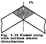 |
We consider first the thickness effects at the centre section, to extend the results obtained in Section 4.3. A non-lifting swept wing of infinite span with a kink at у = 0 can again be replaced by a distribution of sources and sinks of strength q(x, y) per unit area. It can be shown that the boundary condition (2.23) still applies, and so the local source strength is related to the local streamwise slope of the wing section. But elemental source strips have a kink in the middle. Consider now the midpoint of a kinked strip covered uniformly with sources, as shown in Fig. 4.18. For zero angle of sweep, the value vx(0,0,0) at the midpoint is zero because there is always a source element on one side to counterbalance the effect of another on
the other side. With a kinked strip, however, only the sources in the shaded area counterbalance each other. The remaining sources induce a local velocity increment which is directed against the mainstream and proportional to the local source strength. Physically, we must expect a strong kink effect which takes the form of an additional streamwise velocity component. It must be proportional to the local source strength and hence to the local streamwise slope of the wing section at the kink.
Mathematically, this local term can be obtained as the limit z -»■ 0 of vx(x,0,z) (D KUchemann (1947)) or as the limit у 0 of vx(x, y,0)
 |
(S Neumark (1947)). The complete velocity increment along the centre line can then be shown to be
![]()
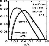
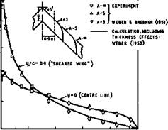
using (2.23) and the Riegels factor from (4.44) to avoid an infinite velocity at the leading edge. The accuracy of this approximation can be checked and improved by the iterative method described above, computing the velocity increment directly on the surface of the thick wing. A typical example is shown in Fig, 4.19. We find that the approximations need only small corrections, but that the pressure distribution at the centre у = 0 is very different from that further out on the wing at y/s =0.5 , which is close to that over
|
Fig. 4.19 Pressure distributions at two sections of an untapered sweptback wing without lift. |
an infinite sheared wing. Thus the centre effect is very pronounced and an essential feature of threedimensional swept wings.
A similar effect must occur near the wing tips. To a first order, the tip section itself behaves like the centre section of a wing with the reverse angle of sweep but with vx taken for only one half wing, so that (4.88) could be used with a factor 1/2 and q> replaced by – cp. But, as described in Section
4.3, a factor 0.7 is more appropriate. Whereas the centre effect shifts the minimum pressure backward along the chord of a sweptback wing and usually reduces it slightly, the tip effect shifts it forward and usually makes the suction peak higher.
This departure of the pressure distribution from that of the infinite sheared wing inplies that a normal pressure drag acts at the centre of a sweptback wing and a thrust at the tips, because zero drag is obtained only with pressure distributions as on twodimensional aerofoils. The drag can be determined by integration from the pressure distribution or from (2.26). This gives
ACd = 4 cos V f (*>) J dx,
0
or, more generally,
1
ACD * * cos [ (4^ — dX. (4.89)
5 ‘ Jl + (dz/dx)2
This pressure drag ife thus proportional to (t/c) , and we shall see later that this drag can be quite large as compared with other parts of the total drag. However, the overall pressure drag of a threedimensional wing must still be zero in an inviscid incompressible flow (or in any isentropic flow) and so the drag forces in the central region must be cancelled by thrust forces in the tip regions. It must be expected that the drag is highest at the centre
section and that it will fall off with increasing у, to be measured in terms of the local wing chord:
![]() ACD(y) = У ACD(y = 0)
ACD(y) = У ACD(y = 0)
 |
|||
There is no need to determine this fall-off very accurately since any approximate interpolation can readily be improved upon by the iterative method of Section 4.3. Physically, nothing much happens between the significant centre and sheared-wing stations, anyway. Any reasonable interpolation curve with у = 1 at у = 0 and у = 0 at about y/c = 0.5 like that shown in Fig. 12 of D KUchemann & J Weber (1953) and repeated in the ESDU Data Memorandum (Anon (1963)) will be quite sufficient. Similarly, another interpolation curve can be used inboard of the wing tips. If the velocity at the wing tip is taken as approximately 0.7 times that from (4.88), then y(yi – у) should have the value 0.7 at у = yp and should fall to zero somewhat further inboard at about (yT – y)/c = 0.75 , say, so that the drag and thrust forces can cancel one another. An approximate formula has been given by J Wooller (1963, unpublished):
у being zero everywhere else.
The same interpolation factor y(y) can also be used as a factor multiplying the centre term (containing f (cp) in (4.88)) to calculate the velocity or pressure distribution at any intermediate station. It can also be used in an approximate way to determine the induced velocity component Vy in the lateral direction. Thus the complete velocity field will produce streamlines as in Fig. 4.6 , starting with a straight streamline along the centre, acquiring curvature away from the centre, and approaching that typical of sheared wings of infinite span near mid-semispan – if the aspect ratio is large enough – and then straightening out again somewhere just outside the wing tips.
Thus we find that the concept of an infinite sheared wing is still useful and may be applied to some region around mid-semispan, outside the regions dominated by the centre and tip effects, if the aspect ratio is large enough. But centre and tip effects will merge and leave no sheared part on the wing when the aspect ratio is about three or less. The flow over the wing is then wholly threedimensional, and properties derived for twodimensional aerofoils can no longer be applied.
We have considered compressibility effects several times already, in Section
2.3 and in Section 4.2 for infinite sheared wings. Now we have to consider the full potential equation for threedimensional flows, given by (2.2). We have seen that the simplest way of obtaining solutions is by the Prandtl – Glauert procedure in which an analogous wing of reduced thickness, higher sweep, and smaller aspect ratio is considered through the relations (2.32), (2.33), and (2.34). This means that we are now getting interested also in wings of smaller aspect ratios, when the Mach number is increased, even if the aspect ratio of the actual wing is still large. This implies, in turn, that the part of the wing where infinite-sheared-wing concepts may be applied will shrink as
139
 |
the Mach number increases. For example, on a wing with a geometric aspect ratio of 6, it would disappear altogether at a Mach number of about 0.87, if the Prandtl-Glauert rule (4.19) is applied. In reality, the flow will be wholly threedimensional at a lower Mach nuniber, since the actual answers from the Prandtl-Glauert rule are usually quite inadequate. The results in Fig. 4.20 show that Weber*s rule (i. e. (2.38) suitably adapted) gives a much better representation of experimental values. This implies that the curves in Fig.4.7 can only serve to illustrate trends; numerically, they are not correct.
The Weber rule has been extended to threedimensional wings where it turns out that the compressibility factor 3 cannot be applied everywhere but takes different forms for the centre, sheared-wing, and tip regions. These compressibility corrections have been revised by R C Lock (1970) on the basis of the work by R C Lock et at* (1968) for twodimensional aerofoil sections. Different factors are now applied to the first-order and the second-order terms in the RAE Standard Method, but the new factors are largely empirical and could only be based on plausible suggestions. They must, therefore, remain tentative in some respects until reliable experimental evidence becomes available.
We shall come back to these problems in Section 4.8. But it is already clear that, even when the flow remains wholly subcritical, compressibility effects on threedimensional wings are large.
Having found strong threedimensional centre and tip effects on thick swept wings at zero lift, we may expect that similar effects occur on lifting wings, even if we restrict ourselves first to wings of large aspect ratio in inviscid incompressible flow. We retain the same vortex model as in Section 4.3 and, in particular, the concepts of bound vortices, y^ , which now lie spanwise along the direction of sweep, and of trailing or streamwise vortices yt. We also retain the concepts of effective and induced angles of incidence, ae and df, and write the boundary condition on the wing as in (4.57). This implies that, with the assumption (4.51) for wings of large aspect ratio, we still take the downwash induced by the streamwise vortices to be constant along the chord. On a swept wing with a kink in the middle, the streamwise vortices are staggered and begin at different values of x, depending on the spanwise station у. If the spanwise loading is such as to produce a constant induced downwash ot£ along the span of the wing as well as in the Trefftz plane, the vortex drag has a minimum given by (3.22). If this spanwise loading would also correspond to a constant C^-value along the span, as on unswept wings with elliptic planform and elliptic loading, then Cpy ■ CL ai and d£ would be given by (3.24) or, more generally, by (4.56) and (4.57). This means that the
downwash from the streamwise vortices would he independent of the angle of sweep and remain the same whether the streamwise vortices are staggered or not. This simplification that there is no sweep effect on the streamwise vortices is made in the approximate method that follows.
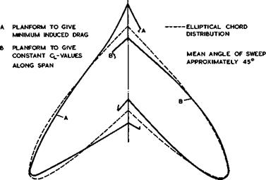
We note at this point that this rather drastic simplification must imply some errors. If the theory to be derived on this assumption is applied inversely to calculate, for example, planform shapes to give elliptic spanwise loading and hence minimum vortex drag, and also planform shapes to give constant lift along the span, it turns out that the planform shapes are not the same when
|
Fig. 4.21 Calculated planforms for minimum induced drag and for constant lift |
the wing is swept. These two characteristics go together only when the wing is unswept; if the wing is swept, the two planforms differ significantly as the example shown in Fig. 4.21 indicates. Thus this approximation is, strictly, not self-consistent. Even so, we shall find that the error is small, because the main effect of sweep is that caused by the change of direction of the bound vortices near the central kink of a swept wing, in much the same way as the kink effect of source lines. This affects the value of ae and leads to a chordwise loading which differs radically from that for a twodimensional
|
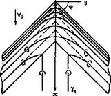
Fig. 4.22 Vortex pattern near the centre of a sweptback wing |
aerofoil, or for an unswept wing, as given by (4.54).
 |
That there must be a strong effect of the central kink becomes quite clear when we look at the likely vortex pattern песет the centre of a sweptback wing of large span, as indicated in Fig. 4.22. It is evident that the simplifying assumption (4.51) for wings of large aspect ratio is not now admissible. For a flat wing (full lines), the bound vortex lines must change direction and curve round smoothly, and some may even turn into streamwise vortices before they reach the kink. In that case, the loading at the centre will be lower than that further out on the wing. All this is likely to happen within about one chord from the centre line; further away, conditions as on an infinite sheared wing will be approached. A wing must be specially designed and shaped to have the same chordwise loading at all spanwise stations, right into the middle (dashed lines). The bound vortices then have a kink at the centre line.
using (4.92). The first term is equivalent to (4.53) for unswept wings and the second term expresses the remaining downwash as being proportional to the local vortex strength. Thus kinked source and vortex distributions, to represent thickness and lift, exhibit similar centre effects. These are the significant features of threedimensional swept wings, which demand our attention above all.
At the centre, у = 0, some numerical evaluations of the actual downwash integral for specific wings of small thickness have shown that the function cr(<p, x,y, z) can be approximated simply by
a = it tan <p, (4.94)
i. e. by a function of <p only, for any given shape of the wing section. J Weber
(1957) and (1973) has evaluated in detail the error introduced by this approximation.
To see what has to be done to counteract this strong centre effect, consider a swept wing of infinite span where we demand that the chordwise loading be that of the twodimensional flat plate everywhere along the span, including the centre, so that no trailing vortices are shed:
*(x) =f (4’95)
for all values of у, as in (4.54), with the chord c taken as unity. Inserting this into (4.93), with a from (4.94), we find that the downwash integral can be evaluated in closed form:
With the boundary condition vze/V0 = dz/dx, the coordinates z(x) of the shape of the centre line of the aerofoil section at the central kink of the wing can be obtained by integration:
if z(0) = 0. Far away from the centre at the sheared part of the wing, only the first term in (4.93) applies and we have
cL
z(x) = a x, where a = – z—– , (4.98)
zir costp
in accordance with (4.17), since a = ae in the absence of trailing vortices. The difference in the shape of the chordline between the centre section and a section on the sheared part of the wing can then be determined and divided into two parts:
Да = Az(x=l) = у a tan<p, (4.99)
which represents an angle of twist, and
Az(x) – Дах = іа tan <p 0 – 2x) – sin 1 (1 – 2x) + Jl – {I – 2x)^| (4.100)
which represents a camber tine. In these expressions, a (and thus Cl) and <p appear only as factors so that the twist and camber take the same forms under all conditions. The camber line has its position of maximum camber at 29% of the chord. The camber at the centre of a sweptback wing is negative, i. e. concave on the upper surface. The twist is in the sense of increasing the angle of incidence at the centre above that of the sheared part of the wing. That (4.99) and (4.100) are adequate approximations has been demonstrated experimentally by shaping a wing (with <p = 45° and A = 5, t/c = 0.12) accordingly and testing it. Flat plate loadings were measured everywhere for angles of incidence between about -2° and +10° (see J Weber & G G Brebner (1951),
D KUchemann (1953)). We may conclude quite generally that camber and twist are needed to load up the central region of a threedimensional sweptback wing to obtain the benefits of sweep as exhibited by an infinite sheared wing.
These design matters will be discussed further in Chapter 5. .
We now proceed to consider wings of arbitrary given shape and make the assumption that the downwash induced by the bound vorticity component can still be approximated by (4.93), with a from (4.94). For example, if ae = vze/V0 = constant at the centre section, as for a flat wing, this relation can be regarded as an integral equation for y(x) or £(x) of the type treated by T Carleman (1922). But the relation (4.92) between vortex strength and loading
cannot be applied at the centre section because the elemental vortex lines must be expected to cross the centre line at right angles, as in the full lines of. Fig. 4.22, and thus be unswept there. Hence
|
y(x) = Jv0 *(x) , |
(4.101) |
||
|
The solution for |
the loading is then |
||
|
*(x) |
– sinim c/*1 " Xt 7ГП Цх – ^ J |
» |
(4.102) |
|
n = i(1 ■ ¥72} |
(4.103) |
||
|
<г “e |
, costp » a e 47m. sinim |
(4.104) |
|
as in (2.46). |
for the sectional lift slope. This fits well into our framework of classical aerofoil theory: it has exactly the same form as (4.54) for unswept wings of large aspect ratio, where n ‘ j, and as (4.71) for unswept wings of small aspect ratio, where n’ is obtained from (4.80). The Kutta condition at the trailing edge, A(xx) = 0, is fulfilled automatically.
The threedimensional sweep effect is thus described by the single parameter n from (4.103). It varies linearly with sweep angle from n = 1 at q> = -90° to n = 0 at <p ■ +90° . It also determines the behaviour of the load near the apex of the wing. The exact mathematical behaviour near this singular point has exercised many (see e. g. P Germain (1955), R Legendre (1956), Patricia J Rossіter (1969), Susan N Brown & К Stewartson (1969), R S Taylor (1971), Patricia J Davies (1972)), and it is now clear that, for P >0, the loading near the apex does indeed behave like (l/x)n, as in (4.102). But it turns out that n is not strictly a linear function of <p between n <* J for p * 0 and n = 0 for ф = +90°, as in the approximation explained above, but the deviations are not large. This result is of interest also in the application of methods for computing the loading over swept wings by the use of collocation points: representing in the computer program both the singularity of the load at the apex and the detailed behaviour of the load near the apex leads to large increases in the accuracy or, alternatively, to considerable savings in computer time, as has been demonstrated by В L Hewitt & W Kellaway (1972).
The threedimensional effect on the chordwise loading over the centre of a swept wing is quite strong. A typical example is shown in Fig. 4.23. As for the case of a thick wing at zero lift in Fig. 4.19, the velocities are reduced over the front part and increased over the rear part, as compared with those over a twodimensional or sheared aerofoil, which is consistent with the general flow model drawn in Fig. 4.6. One is tempted to say that the front part is "under-twodimensional" and tends to the behaviour of a threedimensional body, whereas the rear part is "over-twodimensional", with regard to both thickness and lift. Thus the kink effects of thickness and of lift reinforoe each other. Fig. 4.23 also shows that the approximation (4.102) represents experimental values well and that the shape of the loading curve is not strongly affected by the aspect ratio of the wing, in the region tested. The turning of the bound vortices in the central region evidently produces the overriding local effect, as is to be expected.
This characteristic feature can be exploited in order to interpolate the loadings at other stations near the centre. At some distance away from the centre
5
![]()
![]()
![]()
![]()
![]()
![]()
![]()

 О
О
on the sheared part of the wing, (4.92) applies and the chordwise loading is given by (4.54). We find that (4.102) formally covers both cases, n – applying to the sheared wing, у » c, and n from (4.103) to the centre section у – 0. Therefore, we simply assume that this relation applies everywhere and that a reasonable interpolation can be obtained by regarding n as a function not only of cp but also of у, to be measured in terms of the wing chord. Within the present simple framework, it does not seem worthwhile to go further than that and, again, nothing much of physical significance happens between the centre and sheared-wing stations. To stay safely on physical grounds, however, we use the fact that the position of the aerodynamic centre is xac/c « J(1 – n), by (4.72), and that the locus of the aerodynamic centre along the wing span can be expected to be a smooth continuous line which crosses the centre line of the wing at rightangles. For a flat wing of infinite span, this locus can reasonably be approximated by a hyperbola with the quarter-chord lines of the two wing halves as asymptotes. If we now
![]()
![]() (4.105)
(4.105)
as a generalisation of (4.103), the interpolation function X(y) is related to the shift of the aerodynamic centre caused by the effect of the kink at the centre,

(4.106)
which can be further simplified for small angles of <p into
![]() (4.107)
(4.107)
This relation has been found adequate for most practical purposes. X * 1 at the centreline у ■ 0, and X fades out to a small value at about у ■ c,
in accordance with the flow model we have in mind.
The characteristic properties of the central region of a swept wing have been derived in such a way that they can be said to apply also in the tip regions of wings of finite span, with the opposite sign of the angle of sweep, and y/c measured inwards from the tips. In this way, the chordwise loading at any spanwise station of a swept wing can be determined from (4.102), together with (4.105) and (4.107). Similarly, the sectional lift slope at any station is given by (4.104). It then remains to determine the spanwise lift distribution СіДу) . Since we made the assumption that the downwash a£ induced by the streamwise vorticity components is not affected by sweep, the classical relation (4.56) can be used in the generalised form of (4.81). Thus the load distribution over the whole surface of a swept wing can be determined.
The framework of this theory is so constructed that effects caused by low aspect ratios can readily be incorporated by combining the above relations with those derived in Section 4.3, especially with (4.71) for the chordwise loading, (4.74) for the sectional lift slope, and (4.80) for the parameter n (see D KUchemann (1952)). That this is possible is based on the physics of the flows which have many fundamental similarities. Again, the effects of non-zero wing thickness and of compressibility can be incorporated, using the relations derived in Sections 4.3 and 4.4, and pressure distributions can be calculated. The application of camber and twist needs special treatment in this framework (see G G Brebner (1952)), as does the inclusion of wing taper and of any cranks in the leading and trailing edges at spanwise stations other than the middle of the wing (see G G Brebner (1953)).
When all these elements are combined and the various terms put together, a complete relation can be obtained for the velocity at any point on the surface of any given thick, lifting, swept wing in compressible sub critical flow. This may be found in detail in the extensive ESDU Data Memo (Anon (1963) and
(1973) ), together with explanations of how it should be used. A complete and consistent set of all the second-order terms for wings in incompressible flow has been derived by J Weber (1972). The accuracy of this RAE Standard Method has been assessed by J Weber (1973). It can readily be improved by the rapidly-converging iteration method of Weber and Sells, which has been described in Section 4.3. To account for compressibility, the Weber factor from
(2.38) can be extended to threedimensional wings and incorporated. Alternatively, compressibility factors proposed by R C Lock et al. (1968) and R C Lock (1970) can be used, whiah should lead to an improvement over the local linearisation. But this includes an empirical element, and it is still not clear whether or not the compressibility factors give a sufficiently accurate approximation, especially near the centre of a swept wing. Doubts have arisen ever since T E В Bateman & A J Lawrence (1955) produced experimental results which indicated that the actual centre effect at near-critical Mach numbers was more pronounced than in the theoretical estimates (see also A J Lawrence (1954)). These have not yet been resolved. The main characteristic of the RAE Standard Method described here is that all the terms in a rather complex formula can be interpreted and have some physical meaning. The iteration method to obtain accurate answers has the merit of retaining a "feel" for the accuracy of the results, since residual errors are known at all stages in the calculation.
A typical calculated pressure distribution over the surface of a sweptback wing is shown in Fig. 4.24, which can be compared with that over an unswept wing in Fig. 4.15. The threedimensional sweep effects are seen to be very
Pressure distributions over a sweptback wing of large aspect ratio

 |
|
large, and the pressures now vary considerably along the span. The reduction of the suction peaks in the central region and the very sharp and high peaks in the tip regions are particularly noticeable. Such non-uniformities are obviously undesirable in wing design. Among other things, they produce unnecessarily steep adverse pressure gradients and hence premature flow separations; and also unnecessarily early appearances of local supersonic regions. How these shortcomings may be avoided by suitable wing design and, in particular how the centre and tip effects may be counteracted will be discussed in Chapter 5.
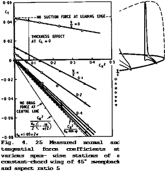
A very sensitive check to show whether or not the pressure distribution along some section has a twodimensional character is to plot the sectional tangential force coefficient Cj against the square of the sectional normal force coefficient Cj^ . Extending (3.30) for uncambered wings, we should have
CT = “ CN2 . (4.108)
with a from (4.104) and n from (4.105). The tangential thrust force would be large enough to bring the sectional drag force in inviscid flow to zero if
CT —– — cJ2 (4.109)
T aQ cos ф ті 4 ‘
on the sheared part of the wing; and if
![]()
![]()
![]() CT = "
CT = "
at the centre section. Experimental evidence in Fig. 4.25, which is to be compared with that in Fig. 4.16 for unswept wings, shows that values according to
(4.109) are indeed approached for the larger values of y/c of about 1 or greater, i. e. there exists a sheared part on this wing, where the properties are closely related to those of the corresponding twodimensional section. But
(4.110) obviously does not apply. In fact, it can be shown that Op " 0 for the chordwise loading at. the centre, by (.4.102) (see D KUchemann (1952)), so that there is a large drag force due to lift at the centre section. By (3.29), this drag force gives 4CD = CLae. In addition, we have already seen that there is a drag force due to thickness, given by (4.89). The experimental results in Fig. 4.25 confirm this and show at the same time how the drag is built up towards the centre. The linear relationship between c2 and CT appears to be retained, however.
We note at this point that there are many other methods for calculating the loading over swept wings, usually for incompressible flow. The emphasis is not so much on the physics of the flow but mostly on the numerical aspects and the use of computers; some of them have already been mentioned in Section 4.3.
In some other methods, the wing is replaced by a lattice of vortex lines, or panels of sources or doublets, in contrast to the method described above where the load distribution is continuous over the whole surface. The boundary condition is thensatisfied at collocation points within such lattice elements.
The accuracy of vortex-lattice methods is sometimes doubtful (see D KUchemann (1952)). Typical of this kind of method are those by S G Hedman (1965), F A Woodward (1968), E Albano & W P Rodden (1969), W P Rodden et at. (1971) and
(1972) . Other practical methods have been developed by A Kraus & T Sacher (1970) and В Maskew (1970) and (1975). In these methods, collocation points or panels are treated in an egalitarian manner, for the sake of the computer, and the physical significance of kink and sheared-wing sections has been suppressed and does not appear. None of these methods has been specifically designed to reproduce the correct behaviour at kinks, cranks, and other significant regions, except that by В L Hewitt & W Kellaway (1972), which has already been mentioned. Numerical solutions of potential-flow problems can also be obtained by finite-element methods. A discussion of the mathematical problems involved may be found in J R Whiteman (1973). A practical finite-element method has been developed by J H Argyris & G Mareczek (1972).
Another set of methods uses distributions of singularities over the surface of the given body. These are powerful tools, where the emphasis is again on the numerical analysis – the fundamental aerodynamics are the same as in the classical treatment describe above, and no new physical concepts arise or
are involved. In fact, the various physical effects and significant mathematical behaviours which have been identified above do not appear and come out clearly. It would seem to be a job for the numerical analyst in the future to identify the behaviour in all sensitive regions and to feed this into the computer program intentionally and carefully.
The pioneer work on ’panel methods was done by J L Hess & A M 0 Smith (1967).
The shape of the body is approximated by a number of plane quadrilateral panels – or faoets – whose corners are derived from the set of points used to define the body. Each panel carries a uniform source distribution. The source strength is determined from the boundary condition that the velocity component normal to the panel vanishes. Thus the velocity components induced by each source panel at all the others (including its own) are calculated first, and the boundary condition is then satisfied approximately at one control point on each panel, normally taken to be its centroid. These conditions can be expressed in matrix form, with a matrix of influence coefficients. Because of the simple way in which the problem is discretised, analytic expressions for the velocity vectors and influence coefficients can be determined. These expressions are rather complicated and hence time-consuming to compute. They are used only at points close to the centroid of each element, and a multipole expansion is used for more distant points. The unknown source strengths are then obtained by solving a set of linear equations. If the number of panels is not too large (less than about 500), direct Gaussian elimination can be used; for larger numbers, standard iterative relaxation methods are usually successful. When the source strengths are known, the total velocity at each panel can be computed. Lift has been introduced into this method by J L Hess
(1972) by placing a distribution of vorticity of unit strength on each panel.
On a threedimensional wing, the surface is subdivided into a number of chord – wise strips of bound vorticity and a trailing vortex wake is added. The procedure of obtaining solutions for the superposed source and vortex distributions is otherwise the same as that for non-lifting bodies. The Kutta condition at the trailing edge is not fulfilled automatically, as in the RAE Method. Therefore, a number of solutions is considered in succession until the Kutta condition is satisfied to some suitable approximation, for example, by requiring that the velocities at the two control points immediately adjacent to the trailing edge, on the upper and lower surfaces, shall be equal. This method by Smith & Hess has been applied successfully to many complex configurations, including multiple aerofoils, and it still remains one of the best methods available.
There are now quite a number of other facet methods, and we mention here the early work of P E Rubbert & G R Saaris (1972) and that of S R Ahmed (1973). A similar technique, but with important improvements with regard to the numerical treatment, was developed by T E Labrujere et al. (1970). In this NLR Method, source panels on the surface are used as before, but the lift is represented by a system of quadrilateral vortex panels placed inside the wing, usually on the camber surface. The vortex wake is modelled as a number of discrete vortex lines, one for each chordwise strip of the wing. The combined flow of the source panels and the vortex system is determined in such a way that the Kutta condition is satisfied at control points just downstream of the trailing edge on the bisectors of the local trailing-edge angle. This condition appears to conflict with the result of К W Mangier & J H В Smith (1970), which says the vortex sheet must leave the trailing edge parallel to either the upper or the lower surface of the wing. The important feature of the NLR Method is an improved numerical technique for solving the large number of simultaneous equations for the source and vortex strengths. An iterative scheme of block relaxation has been devised, which leads to a dramatic reduction in the computing time as compared with schemes where a direct matrix inversion is used. The reduction in computing time may be as much as a factor of 5.
We note at this point that these panel or facet methods still involve quite a number of approximations and cannot, therefore, he regarded as numerically accurate. For this reason, the cubic-spline method of A Roberts & К Rundle
(1972) and (1973) is of practical interest because it should be inherently more accurate. Although the computing times are longer, it may be competitive with the iterative NLR Method because, for an expected degree of accuracy, a facet method may need about twice as many panels as Robert’s method for computing a twodimensional flow and about four times the number for a threedimensional configuration. Besides, the Kutta condition can be fulfilled implicitly and the correct behaviour at kinks and in wing-fuselage junctions can be represented approximately. In these respects, other panel methods cannot catch up with this increased accuracy merely by increasing the number of panels. The greater accuracy is achieved by representing the body shape not by a number of plane facets but by a surface interpolation scheme based on bicubic врЫпее. Also, the flow perturbations are produced by continuous distributions of sources and doublets, again built up from a number of basic spline modes. For non-lifting bodies, the procedure is otherwise similar to that used in the facet methods, leading to a set of linear equations for the strengths of the source modes. These are solved by direct matrix inversion. Lift is introduced by means of doublet sheets which cover the wake and extend forward inside the wing along its camber surface. Both the doublet and source strengths vary in particular ways as the trailing edge is approached so that the velocity remains finite there. All these features represent clear improvements over the corresponding parts of facet methods. On the other hand, the velocity fields and the influence functions can no longer be expressed analytically. They are now surface integrals over the panels, and these are evaluated numerically by means of a double Gaussian quadrature, successively subdividing the panels in both directions until adequate accuracy is obtained. As a result of this complexity, the computing time is much longer than that of the facet methods.
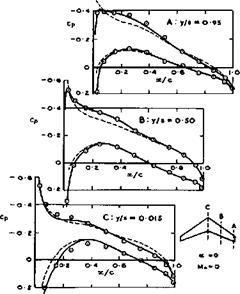
In general, results of good accuracy can be obtained by the cubic-spline method of Roberts & Rundle, at least for incompressible flows. The accuracy is about the same as that of the iterative method of Weber and Sells described above. This has been demonstrated by С C L Sells (1974), and an example is reproduced in Fig. 4.26 (see also R C Lock (1975)). This sweptback wing has been designed by J A Bagley (1965) to have straight isobars at Mq = 0.8 and Cl = 0.35, but the calculations have been made for Mq = 0 and a = 0. The wing has a simple planform and thickness distribution but the camber and twist distributions are complicated, with a. j. = 7° at the wing centre, aT = 2° around mid-semispan, and aj = 0 at the tips; the camber is strongly negative at the centre and strongly positive at the tips. It will be seen from Fig.
4.26 that the chordwise pressure distributions calculated by Sells’s method (circles) agree well with those calculated by Roberts’s method (full lines).
The dashed lines show the results of linearised theory. The computing times of Sells’s method are relatively low, about one third of those of Roberts’s method and, perhaps, two or three times those for the calculations according to linearised theory.
An alternative, method is to represent the surface of the aerofoil by vortex elements. This was first done by W Prager (1928) and then developed further by К W Jacob (1962) and D H Wilkinson (1967). A powerful and well-conditioned
surface-vortex method is that of T Seehohm & В G Newman (1975). Rubbert’ s method has also been extended into a more powerful and rapid tool by F T Johnson & P E Rubbert (1975), which requires fewer panels to reach the same accuracy
 LIVE GRAPH
Click here to view
![]() Pressure distributions over a sweptback wing. After R C Lock (1975)
Pressure distributions over a sweptback wing. After R C Lock (1975)
as the earlier method. Either sources or doublets may be put on curved panels, and the strengths of the singularities vary as polynomials. No special precautions are taken near leading edges, kinks, or junctions, and so uncertainties are likely to arise in these regions. The method may be used for analysis as well as for design. J L Hess (1973) has extended the method of A M 0 Smith to include higher-order terms. It may not be unreasonable to expect that many of the present methods, with the emphasis firmly on the numerical aspects, will be developed further, with more attention paid to the physical features of the flows, as is done in the RAE Standard Method.
All these numerical methods need to be accompanied by suitable programs to describe or to generate the geometry of the configuration, not only for analysis but also for design (of windtunnel models and of real aircraft). More work is needed to arrive at numerical programs which are consistent and coherent, flexible and adaptable, for practical purposes.
There is a whole field of work concerned with unsteady flows past wings and with the aeroelastic behaviour of deformable wings and bodies. A discussion of these problems goes beyond the scope of this book, and we refer to some recent AGARD publications (1971) and to E C Pike (1971) and to H G KUssner (1973) for theories of oscillating wings. Fundamentals of aeroelasticity have been dealt with by H W FSrsching (1974). В A Hunn (1952) applied the concepts of the RAE Standard Method to derive a method for estimating the loading on an elastic airframe.


