Vertical Drag and Download Penalty
It is normally assumed that the total thrust, T, required by the main rotor is equal to the weight of the helicopter, W. However, there is usually an extra increment in power required because of the download or vertical drag, Dv, on the helicopter fuselage that results from the action of the rotor slipstream velocity (i. e., now the rotor thrust will be T+AT = W+Dv). See Wilson (1975) for a good summary of the basic problem. Typically, the vertical download on the fuselage can be up to 5% of the gross takeoff weight, but it
can be much higher for some rotorcraft designs such as compounds or tilt-rotors that have large wings situated in the downwash field below the rotor. In its simplest form, the vertical drag can be accounted for by assuming an equivalent drag area fv or a drag coefficient C0u based on a reference area, say Sref. This means that the extra rotor thrust to overcome this drag will be
AT = DV= pv2f„, (6-29)
where v is the average velocity in the rotor slipstream.
In the first instance, the simple momentum theory can be used to estimate v. It is known that the rotor wake contracts very rapidly below the rotor, so that the airframe can be assumed to operate in the fully developed vena contracta; in the hover condition this velocity is twice the induced velocity at the disk. In a vertical climb, the induced velocity at the rotor will be given using Eq. 5.15, which for normal rates of climb is approximately
— = 1 – (6.30)
vh 2vh
Because the wake velocity v is given by v — Vc + 2u,-, then using Eq. 6.30 it is apparent that v = 2 Vh, that is, v is independent of climb velocity Vc. This means that the rotor thrust will be
T = W + DV = W+ l-pv2f„ = W + Ipvlf, = W + T (A) . (6.31)
Rearranging and solving for the rotor thrust T gives
![]() T = (-^______ Ї___ V
T = (-^______ Ї___ V
1 – fv/A) 1 — SVef CdJAJ
From this result, the net rotor power requirements can be easily calculated using
which is valid for low to moderate rates of climb, assuming the validity of Eq. 6.30. It will be apparent, fortunately, that because /„/A < 0.1 then the airframe drag makes only a modest additional contribution to the total power requirements in climbing flight.
Because of the bluff-body nature of the flow about the fuselage, estimates of the vertical drag can only be reliably obtained from wind tunnel testing of isolated fuselage models. Precautions should be taken to properly represent the nonuniformity of the rotor downwash, as well as Reynolds number effects on the fuselage, the latter which can be difficult to
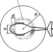
In the second instance the vertical drag on the fuselage can be calculated by estimating the drag coefficient of individual 2-D fuselage cross sections (i. e., a strip approach), as shown schematically in Fig. 6.26, which is suggested by Stepniewski & Keys (1984). The vertical drag of the entire fuselage can then be obtained by successively testing 2-D cross sections of the fuselage to determine the pressure distributions and then finding the net drag on the fuselage by summation. For example, the incremental vertical drag on any one segment of the fuselage of length dl and width w will be
![]() dDv = ^pv2CDvw dl,
dDv = ^pv2CDvw dl,
2.
where v is the local downwash velocity (from the fully developed rotor wake) at the element and Cdv is the drag coefficient. The net vertical drag will be given by
![]()
![]()
![]()

 |
(6.35)
where it is recognized that Cov and v will vary between cross sections. Generally, it is found that helicopter fuselage cross-sectional drag coefficients average out at about 0.5, although the addition of sponsons or stub-wings can increase the drag coefficients to over unity. Wilson & Kelly (1983, 1986) give results for a variety of fuselage cross-sectional shapes, which have been estimated from wind tunnel tests. Drag coefficients for various other bluff – body shapes resembling fuselage cross sections can be found in Delany & Sorensen (1953) and Hoemer (1965).
Note that the strip method of fuselage drag estimation requires an estimate for distribution of the induced velocity in the wake below the rotor. A good first estimate can be made by means of the BEMT discussed previously in Chapter 3. However, because the fuselage also influences the rotor in a reciprocal way, accurate estimates of the interference effects on v are difficult to obtain. The effect of the fuselage is also known to affect the rotor performance, increasing the thrust as the fuselage is brought closer to the rotor – see for example Sheridan (1978), Sheridan & Smith (1979), and Fradenburgh (1972). Because of these effects, and the fact that 3-D effects have also been neglected, the strip method described above tends to be rather crude, at least in theory. Yet, in practice the method has been shown to give fairly reliable estimates of the extra rotor thrust required to overcome fuselage drag in climbing flight.


