HINGE MOMENTS OF PLAIN CONTROL, FLAPS
DEFINITIONS. The hinge moments “H” of flaps, ailerons, elevators and rudders are conveniently presented in the form of the coefficient based on chordwise length, and area of the “flap” portion (measured aft of the hinge line):
Сц ~ H/(q Sf Cp); where: = Ь(с^Г (18)
In configurations where c^ is not constant, the mean of (c^)2 is the best reference length to be used for the hinge moment. There is a basic convention in the field of aeronautics to designate longitudinal (pitching) motions and moments as positive when their direction is “nose – up” (and “tail-down”). Positive deflection of a control surface thus produces a “negative” moment. When discussing “large” or “small” hinge moments, the magnitude of the torque, usually resisting positive flap deflection, is meant in the following.
DERIVATIVES. Theory (2) considers a flat plate (with zero thickness) with a portion of the chord near the trailing edge, deflected by the angle “6”, in two-dimensional flow. When deflecting this “flap”, a hinge moment originates, corresponding to coefficients and derivatives as follows:
(a) At constant deflection angle the hinge moment varies corresponding to
CH – (dCM/dCL) CL (19)
This case applies when changing the angle of attack; and the derivative is (for most practical purposes) independent of the aspect ratio.
(Ы At constant lift coefficient (id est, when compensating flap deflection in one direction, by a change of the angle of attack in the other direction) the moment cor responds to
CH = (dCH/d<0 S (20)
Note that for = constant, the induced angle of attack is constant. The function of dC^ /d6 as in figure 8, can thus also be considered to be independent of the aspect ratio. The two derivatives (a) and (b) appear to be the most perfect form to present hinge moments. The NACA has been using, in practically all publications, different forms, however:
(c) At constant angle of deflection, the moment varies corresponding to
= Cq^od, where Сцх = (dCq/MCL)(dCL/doO
Since dC^/doc is a function of the aspect ratio, the derivative grows in magnitude as the aspect ratio is increased.
(d) At constant angle of attack, the hinge moment varies as a consequence of flap deflection as
CH-CHi4 (22)
where Cp£ =. combined derivative, due to 6 plus due to Cl produced by 6 . This derivative is thus
Ch6 dCH/d6 +(dCH/dCL)(dCL/d<$) (23)
which is again a function of aspect ratio.
The derivatives (c) and (d) have two advantages. They are conveniently determined in wind-tunnel experiments; and they present the two variations of hinge moment in such a manner that their relative magnitude is obvious.
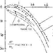
HINGE MOMENT DUE TO LIFT. Experimental results are plotted in figure 7 together with the theoretical prediction. Conclusions are as follows:
(a) Experimental moments are always smaller than those indicated by theory. Presence and growth of the boundary layer are responsible for the difference. Reynolds number, surface roughness and size or shape of the control gap affect the magnitude of the derivative.
(b) The moment is sensitive to section thickness and trailing-wedge angle.
І.0
NACA HOE1TAILS A = 3.5 (I8,g) HORIZONTAL TAILS, see (4,c, d) TAIL SURFACES – OTHER SOURCES VARIOUS SURFACES (2,a)(4,h, i) TAIL SURFACES (4,j)(and(18,a) RECTANGULAR, t/c = 1656 (18,j) NACA SECTIONS (4,1) and(30,c) 2-DIMENSIONAL – OTHER SOURCES NACA 0009 SECTION (4,Ь)(18,е)
Figure 7. Hinge moment of trailing-edge flaps due to lift, for 6 — constant.
(c) The moment reduces with the aspect ratio of the control surface.
(d) It is suspected that test conditions (open-jet as against closed-type wind tunnel) have an effect similar to that of the aspect ratio.
(e) Approaching zero chord ratio, the hinge moment due to lift can become very small. A combination of small A’ratio and* large trailing-wedge angle reverses the direction of the moment altogether.
Details of the various effects listed will be presented later.
|
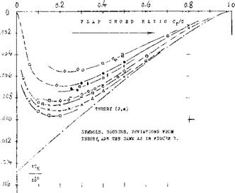
Figure 8. Hinge moment of trading-edge flaps due to deflection, for Cj_ =. constant. |
THE HINGE MOMENT DUE TO FLAP deflection (at constant lift coefficient) corresponds to derivative plotted in figure 8. Again because of viscosity and the effects listed above, the moment is less than predicted by theory. The scatter of the experimental points is considerable, if not as wide percentage-wise as in figure 7. In comparison to the component due to lift, the moment corresponding to dCp/di is usually larger in realistic control configurations. Also, as mentioned before, tail surfaces predominantly operate at constant lift coefficient. For small and moderate chord ratios, figure 8, therefore, gives most of the information needed in the estimation of the hinge moments of plain elevators and rudders. [80]
HINGE MOMENTS OF LANDING FLAPS. Trailing – edge flaps, used to increase the lift coefficient of wings (see the special chapter on this subject), are a case that might suitably be considered at constant angle of attack. The hinge moment of a flap extending over the entire span of the wing, is then:
CH — CHo T(dk p/d6 )6 T(dCp/dCp)ACp (24)
where Сцс represents a certain basic moment due to shape (camber) of the foil section involved and corresponding to the original lift coefficient. The last term in the equation can be written as a function of the deflection angle:
A~ (dCq/dCL )(dCL/do()(do(/d6 )6 (25)
The lift-curve slope in this equation corresponds to the wing’s aspect ratio; see the chapter on “wings”. The dcx/d6 ratio is indicated in figure 2. As mentioned above, the combined derivative (equation 23) is also frequently reported in connection with control surfaces,
EXAMPLE. We will assume a tail surface at constant angle of attack, having a lift angle doCdCp — 16 . The chord ratio of elevator or rudder, respectively, may be Cp/c ~ 0.33. We then find from the various graphs:
(dCH /dCL) .= – 0.03; (dCH /d<S°) = – 0.007
For (X = 0 , the component of the hinge moment due to lift is then found through the use of equation (25):
A(dCH/dcS°) – – 0.03(0.58)/16 = – 0.001
The total moment (at constant angle of attack) corresponds to
CH£ = – 0.007 – 0.001 = – 0.008
As mentioned before, the component due to lift is but small in comparison to that due to flap deflection. It should be noted, however, that the values in figure 7 increase with the chord ratio, while those in figure 8 reduce, at chord ratios above 0.2 (eventually to zero). The derivative dC ^ / dCp could therefore not be disregarded in flaps with unusually high chord ratios.
STICK-FREE CONDITION. We will consider an airplane with a control system which is completely mass – balanced and free of mechanical friction. When the control stick of that system is left free, the elevator (and/or the rudder) will assume a certain deflection angle at which the aerodynamic hinge moment is zero.
CONTINUED
![]()

 That angle corresponds to
d6 /dCL = – (dCH /dCL )/(dCH /d6 ) (27)
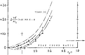
Points evaluated from experiments, through the use of this equation, are plotted in part (A) of figure 9. The divergence of these points from the theoretical function is similar to that in figures 7 and 8. Below c^/c = 0.2, d6/dCj_ becomes very small. Depending upon aspect ratio and trailing wedge angle, to be discussed later, the derivative d& /dC^ can also change direction, which means that the control flap would tend to move against the oncoming flow.
l. o
|
Figure 9. Stick-free characteristics of control surfaces as a function of their flap-chord ratio. |
STICK-FREE STABILITY. Considering a horizontal tail surface, its stabilizing effect dCj_/dc< is usually reduced when leaving the control stick free. In a plain flap, the increment of the angle of attack, required to maintain a certain lift coefficient, is
A(dc*/dCL) = – (dA /dCL)(d«/d6) (28)
where (dchdCi_) as in equadon (27). Experimental re-
suits of this increment of the “lift angle” are plotted in part (B) of figure 9. Usually, the increment is positive; and any such increment means a reduction of the lift – curve slope. This destabilizing effect of a stick-free control surface increases as the flap-chord ratio is increased. The fact that below c. f/c = 0.3 or 0.2, a free elevator or rudder can be stabilizing, will be discussed later.


