"Pushers" versus “Tractors”
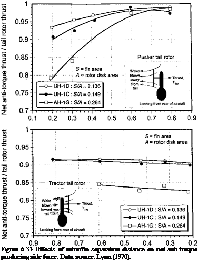
Tail rotors may be either of the pusher or tractor variety and can be located either on the left – or right-hand side of a vertical fin. All designs suffer from interference effects between the rotor and the fin, these effects being a function of the tail rotor size or disk area, A, fin area, S, and spacing of the rotor plane from the fin. The effects are summarized by Lynn (1970), and representative measurements are reproduced in Fig. 6.33 in terms of net anti-torque producing side-force versus fin/rotor separation distance. The results are shown for various ratios of fin area to tail rotor disk area, S/A. In the pusher style the wake of the tail rotor is convected away from the vertical tail. This means that the vertical fin only
Fin separation distance / rotor radius
 |
distorts the inflow into the tail rotor, the consequences of which are a nonuniform inflow and higher induced power requirement. It can also be a source of 2/rev (2Nb) vibratory airloads. In contrast, the tractor design has the vertical fin located inside the high-energy region from the tail rotor wake. While this “blockage” effect tends to increase the tail rotor thrust, there is also a significant force applied to the vertical tail that is in the opposite direction to the anti-torque thrust requirement. It is found, however, that the net effect is a decrease in thrust compared to what would be obtained if the rotor was operating in isolation. In both cases, the interference effects become greater with larger fins and/or smaller rotors. A majority of modem helicopters use a pusher tail rotor design because this configuration tends to have a higher overall anti-torque producing efficiency.


