ZERO-THICKNESS AIRFOIL AT ANGLE OF ATTACK
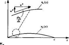
It was demonstrated in Section 4.3 that the small-disturbance flow over thin airfoils can be divided into a thickness problem and a lifting problem due to angle of attack and chord camber. In this section the lifting problem will be addressed, using the classical approach (Glauert,52 pp. 87-93). To illustrate the problem, consider a thin cambered airfoil, at an angle of attack a, as shown schematically by Fig. 5.6. The flow is assumed to be inviscid, incompressible, and irrotational and the continuity equation is
V2<l> = 0 (5.28)
The airfoil camberline is placed close to the x axis with the leading edge at x = 0, and the trailing edge at x = c. The camberline of the airfoil is given by a known function Tfc = r]c{x). The boundary condition requiring no flow across the surface, as derived in Chapter 4 for the small-disturbance flow case, will be transferred to the 2 = 0 plane:
0±) – Q„cos a — sin a) (5.29)
This equation actually states that the sum of the free-stream and the airfoil-induced normal velocity components is zero on the surface
w(x, 0±) – ~ = o.
Also, note that this boundary condition can be obtained by requiring that the flow stay tangent to the camberline (see inset to Fig. 5.6). Thus, the slope of the local (total) velocity w*/u* must be equal to the camberline slope:
 |
 |
w* _ дФ*/дг _drfc и* дФ*/дх dx
Recalling the definition of the total potential Ф* (Eq. (4.9)), this can be rewritten as
where the normal vector n can be described in terms of the camberline rfc:
Enforcing the small-disturbance assumption (e. g., Wx = Q^a, ЭФ/дх « U*,, and (J„ = Q*, cos a = Qx) reduces this to the same boundary condition as in Eq. (5.29).
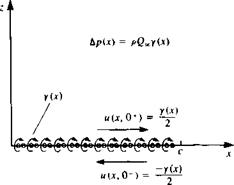
When considering a solution, based on a singularity element distribution, the antisymmetric nature of the problem (relative to the x axis, as in Fig. 5.6) needs to be observed. In Section 4.5, both doublet and vortex distributions were presented to model this antisymmetric lifting problem. Traditionally, however, the solution based on the vortex distribution is used, probably because of its easy derivation and “physical descriptiveness.” Also, the boundary condition requiring that the disturbance due to the airfoil will decay far from it (Eq. (4.2)) is not stated since it is automatically fulfilled by either the vortex or doublet elements. Consequently, a model based on the continuous vortex distribution (as shown in Fig. 5.7) is suggested for the solution of this problem. Furthermore, the vortex elements are transferred to the z = 0 plane, following the assumptions of small-disturbance flow where
To demonstrate the basic features of the proposed vortex distribution, consider a point vortex in the x-z plane, located at a point (jc0, 0) with a strength of y0. Here Yo= v(x) ^ at x = x0 in Fig. 5.7. The velocity potential due to this element at a point (x, 2) in the field is then
 (5.30)
 |
Z A

![]() FIGURE 5.7
FIGURE 5.7
Vortex distribution based model for the thin lifting airfoil.
The velocity due to a vortex points only in the tangential direction, thus
«•=-£ «’-° <5-31>
where r = V(* – x0)2 + z2. The minus sign is a result of the angle в being positive counterclockwise in Fig. 5.7. In cartesian coordinates the components of the velocity will be (и, w) = qe(sin в, —cos 0), or by simply differentiating Eq. (5.30):
 u дфур Го z
Эх 2л (x — x0)2 + z2
п.-дфУ0 Го *-*o
dz 2л (x – x0)2 + z2
Note that if the field point is placed on the x axis, then the velocity above element, normal to the x axis, is
As shown in Fig. 5.7, this problem is being modeled by a vortex distribution that is placed on the x axis with the small-disturbance boundary conditions being fulfilled also on the x axis. The velocity potential and the resulting velocity field, due to such a vortex distribution (between the airfoil leading edge at x = 0, and its trailing edge at x = c) is
![]() Ф(х, z) = – f y(*0) tan-1 ) dxо 2л J0 x – Xo>
Ф(х, z) = – f y(*0) tan-1 ) dxо 2л J0 x – Xo>
Here, y(x0) is the vortex strength per unit length at x0.
|
±r(*) 2 |
Since the boundary condition will be fulfilled at 2 = 0, it is useful to evaluate the velocity components there. The x component of the velocity above (+) and under (—) a vortex distribution was derived in Section 3.14:
for 0<*<c, and this result is shown schematically in Fig. 5.8. The w component of the velocity at z = 0 can be obtained directly from Eq. (5.36) and is
![]()
![]()
![]()
![]() (5.38)
(5.38)
FIGURE 5.8
 Tangential velocity and pressure difference due to a vortex distribution.
The unknown vortex distribution y(x) has to satisfy the zero normal flow boundary condition on the airfoil. Therefore, substituting the normal velocity component from Eq. (5.38) into the boundary condition (Eq. (5.29)) results in
ЭФ(х, 0)
dz
or
This is the integral equation for y(x). However, the solution to this equation is not unique and an additional physical condition has to be added for obtaining a unique solution. Such a condition will require that the flow leave the trailing edge smoothly and the velocity there be finite
Уф
<00 (at trailing edges) (5.40)
This is the Kutta condition discussed in Section 4.7 which can be interpreted now as a requirement for the pressure difference Ap [or y(x)] to be equal to zero at the trailing edge:
y(x = c) = 0 (5.41)
Once the velocity field is obtained, the pressure distribution can be calculated by the steady-state Bernoulli equation for small-disturbance flow over the airfoil (Eq. (5.16)):
P~P~ = – pQ^uix, 0±) = Tp0« ^ (5.42)
The pressure difference across the airfoil Ap (positive Ap is in the +z direction), where above the airfoil
and at the airfoil’s lower surface
![]()
![]() ЭФ
ЭФ
sc-0-)-
is
Ap =Pi~Pu =P
|
r P-P oo Y p kpQl V |
(5.44) |
|
and the pressure difference coefficient is |
|
|
ЛС’’2І |
(5.44a) |
|
The pressure coefficient with the small disturbance assumption then becomes |


