Our heavyweight helicopter equal in the world does not have
In Rostov started production of the most load-lifting rotary-wing car The Russian holding «Helicopt[...]

Everything about aircrafts and helicopters. News and events in aviation worldwide. Civil, transportation, military helicopters and airplanes.

Everything about aircrafts and helicopters. News and events in aviation worldwide. Civil, transportation, military helicopters and airplanes.

Everything about aircrafts and helicopters. News and events in aviation worldwide. Civil, transportation, military helicopters and airplanes.

Everything about aircrafts and helicopters. News and events in aviation worldwide. Civil, transportation, military helicopters and airplanes.


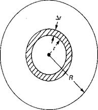
The assumption of a uniform induced velocity distribution simplified the previous analysis, but in order to reflect more accurately actual conditions, it must be replaced by a nonuniform distribution. This distribution can be considered to consist of two effects, a local tip effect due to vortex interference, which will be discussed later, and an overall effect, which can be analyzed by combining the momentum and the blade element systems of analysis at an annulus of the disc, as in Figure 1.18. The increment of thrust on this annulus, AT, is:
AT = pvl2irArv2
 |
2 3 4 5 6
Number of Blades, b
FIGURE 1.17 Effect of Number of Blades on Ideal Figure of Merit as Calculated by Two Methods
Source: Harris & McVeigh, “Uniform Downwash with Rotors Having a Finite Number of Blades,” JAHS 21-1, 1975.
where 2rrrAr is the area of the annulus and vx and v2 are the induced velocities at the rotor disc and in the remote wake, respectively. Just as in the original derivation of the momentum equation, it may be shown that: so that the equation for AT becomes:
AT = 4prr^rAr
From the blade element theory, the increment of thrust can also be written:
Equating the two expressions for AT and arranging the result gives:
a a2
4tv] + — bacv,———- rbaQc = 0
2 2
or
— — acb + J ^—acbj + 8 тЬП2га$с
8 її
This is a perfectly general equation for the induced velocity at any radius, r. It can be used with any twist distribution by using the correct value of blade pitch, 0, at the blade station, and it can be used with any blade taper scheme by using the correct value of the chord, c.
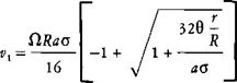 |
For a constant chord blade, the equation can be manipulated to give:
Note: If the analysis is being done for a rotor with cambered airfoils, 0 should be replaced by (0 — aoi) where aoi is the angle of attack for zero lift.
For this case, it may be seen that the induced velocity depends on the radius station only as the parameter, 0(r/R), varies with the radius. If the rotor has ideal twist, then this parameter is a constant being equal to the pitch at the tip:
For blades with constant chord and ideal twist, the induced velocity is a constant across the disc as was originally assumed in the momentum theory. Thus one definition of ideal twist is the twist required for constant chord blades to produce a uniform induced velocity.
The lift distribution corresponding to ideal twist and uniform induced velocity is triangular. This is in contrast to the ideal wing, which produces uniform induced velocity with an elliptical lift distribution. The equation for lift distribution written in terms of the circulation, Г, is:
![]() = cTV = cTOr
= cTV = cTOr
For a triangular lift distribution on an ideal blade, the circulation is a constant; and only two trailing vortices are generated: one at the root and one at the tip.
|
FIGURE 1.18 Geometry off Rotor Annulus |
The nonuniform distribution of induced velocity of a rotor that does not have ideal twist manifests itself in the remote wake as a nonuniform dynamic pressure distribution, which is significant in making estimates of fuselage downloads or ground erosion. Figure 1.19 shows the measured distribution from reference 1.4 for several locations downstream of a full-scale rotor with a linear twist of —4°. It may be seen that the wake contracts very rapidly, accomplishing most of the contraction within the first 10% of radius. The tests were conducted in winds of less than 3 knots, but the test results show that even winds this low can deflect the wake significantly.