
Our heavyweight helicopter equal in the world does not have
In Rostov started production of the most load-lifting rotary-wing car The Russian holding «Helicopt[...]

Everything about aircrafts and helicopters. News and events in aviation worldwide. Civil, transportation, military helicopters and airplanes.

Everything about aircrafts and helicopters. News and events in aviation worldwide. Civil, transportation, military helicopters and airplanes.

Everything about aircrafts and helicopters. News and events in aviation worldwide. Civil, transportation, military helicopters and airplanes.

Everything about aircrafts and helicopters. News and events in aviation worldwide. Civil, transportation, military helicopters and airplanes.


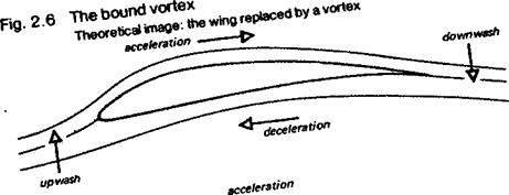
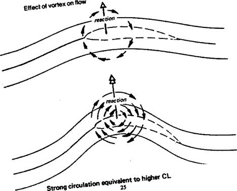
The upwash ahead and downwash behind a wing, with the accelerations and decelerations above and below, suggest that a diagram like that in Figure 2.6 may be drawn. The streamlines behave as if, instead of a wing, there was a rotating and moving cylinder of air, a vortex, with its axis aligned with the wing. Such a cylinder would cause upwash and downwash, acceleration and deceleration of flow, in very much the same way as a real wing, and it would cause identical reaction forces. The strength or speed of the vortex circulation would determine how much reactive force was produced. Many experiments have shown that rotating cylinders do produce lift, but the main value of this idea is that it enables the lifting ability of any wing to be explained or calculated in terms of the strength of circulation of the imaginary vortex. The rotating cylinder is termed the bound vortex because it is supposed to be tied to the wing and moves along with it. The idea of the bound vortex is particularly useful in calculations of the lift distribution spanwise across real wings. The strength of the bound vortex at each point is a measure of the lift at that location. The concept is a mathematical model rather than a physical reality.
2.5 BERNOULLI’S THEOREM
Bernoulli’s theorem connects the pressure measured at any point in a fluid such as air to the mass density and velocity of flow. This theorem is a special application of the laws of motion and energy which is of fundamental importance to aerodynamics and flight, as well as to liquid flows in pipes, channels and around the hulls of ships, etc.
|
|
|
If a small particle or cylinder of air is imagined as part of a general flow moving smoothly, or in ‘streamlineid’ fashion, the particle will be in equilibrium if the pressures acting on it from all directions are equal. If there is a pressure difference in any sense, the particle will accelerate or decelerate in accordance with the second law of motion. V, velocity, will increase if the pressure on the front face of the cylinder is less than that behind, V will decrease if the pressure behind is less than in front. Hence the particle will speed up as it approaches a region of low pressure, and slow down on approaching a high pressure zone. Since it is not isolated, but part of a general streamlined flow, the same laws apply to every particle in the flow, which therefore speeds up and slows down on approaching low and high pressure regions respectively. The simple mathematical expression of this principle is, where P stands for pressure:
P + VipV2 = Constant (Bernoulli’s theorem)
Air flowing at speeds of interest to modellers is constant in density. Pressure and velocity are the only variables; if one increases the other decreases under all circumstances. A well known application of the principle is the ‘venturi’ tube which is used in aviation to measure airspeeds or drive instruments, and in every day life to produce high speed jets from garden hoses, taps, etc.
A fluid passing through a constricted tube such as the venturi sketched in Fig. 2.7 contains no vacant cavities. The same mass of fluid must leave the exit, in each time unit, as the mass entering. In the constricted part of the tube, since the cross sectional area is small, the velocity of flow must increase to get the same mass through in the time available. This increase of velocity, in accordance with Bernoulli’s theorem, produces a reduction in pressure in the throat. The small cylinder of air imagined above becomes elongated and narrower in cross section in the throat, then returns to its original form after reaching the wider part of the tube. The ‘streamlines’ thus appear as shown.
A fluid passing over any body, so long as streamlined flow persists, will experience similar deformations of flow, with accordant velocity and pressure changes. This is particularly relevant to the flow over a wing.
The Figure 2.2 showed, in accordance with Bernoulli’s theorem that when air passes over a wing it accelerates into the low pressure region on the upper surface. Somewhere it reaches the point of least pressure. From there onwards it flows towards the trailing edge against a pressure gradient tending to slow it down. The pressure above the wing behind the minimum pressure point, although it is increasing, is still lower than the normal or ‘static’ pressure of the main flow far away from the wing. On the underside, although the pressure is high on average, there is deceleration up to the maximum pressure point (which is often very close to the leading edge) and acceleration thereafter.


