COMPRESSIBILITY EFFECTS ON CONTROL SURFACES
As discussed in Chapter VII the effect of compressibility in the subsonic range is to cause an increase of the slope of the lift curve below the critical Mach number and a sharp change in both lift and drag above the critical Mach number. Since it is desirable to have no sudden changes in the control characterisitcs of the airplane with changes of speed, compressibility effects are important considerations in the design of control surfaces.
|
|
MACH HO. M
Q L.. -1____ 1——- 1——- 1——- і——— 1—– 1
; .3 4 -5 .6 7 .8 .9
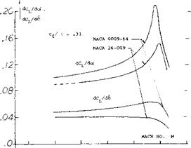
Flap Effectiveness Ratio. As shown on page 9-2, effectiveness ratio of flaps is determined by the ratio of dCL/d6 to dCL/do( or d<Y/d6. For a flapped airfoil two dimensional operating below the critical Mach number tests (51,a) show that both lift curve slopes will increase with the Prandtl-Glauert factor 1//1- Мг. The effectiveness ratio then should not change below the critical Mach number at least for flaps mounted on a two dimensional airfoil. This is illustrated on figure 43 for symmetrical airfoils with a 33% chord flap. The increase of dCL /dot as the critical Mach number is approached is sharper than dCL/d6 as illustrated, so that below Mcr the effectiveness decreases slightly. The important decrease in flap effectiveness ratio illustrated on figure 43 occurs at a Mach number above the critical, and is dependent on the load distribution and where on the airfoil the local shock wave is first formed. Although the lift curve slopes shown on figure 43 apply at angles up to 5°, it can be expected that non-linearities will be encountered at the higher angles.
(41) Charac eristics of Flettner-type flaps:
a) The* servo-tab mechanism was originally patented to Anton Flettner, whose name was occasionally applied to tabs in general.
b) Operation of the simple Flettner-type servo-tab system has been called “sluggish”.
(45) Staufer, Motions of Servo-Tab Control Flap as Function of Time, Ybk D Lufo 1942, 1-308.
(49) Analysis of spring-tab control systems:
a) Brown, Tab Controls, ARC RM 1979 (1941).
b) Imlay, Aileron, NACA W Rpt L-318 (1944).
(50) Experimentation with spring-tab control systems:
a) Zeller, Flap Tab, Ybk D Lufo 1941 p. 1-33.
b) Crandall, Hinge Moments, NACA TN 1049 (1946).
c) Harris, Reduction, NACA T Rpt 528 (1935).
d) Phillips, Elevator, NACA T Rpt 797 (1944).
e) Morgan, Spitfire Tests, ARC RM 2029 (1942).
f) Nivision, Tab Elevator, ARC RM 2268 (1946).
g) ARC, Spring-Tab Ailerons, RM 2059 (1944).
(51) Influence of compressibility upon flap characteristics:
(a) Stevenson, NACA 0009-64 Airfoil with 33.4% Chord Flap, NACA TN 1417.
(b) Stevenson, 9% Foil Sections, NACA TN 1406 & 1417 (1947).
(c) Lindsey, 9% Foil with 30% Flap, NACA RM L56L11.
(d) Lowry, Rectangular Wings, NACA RM L56E18.
(e) Whitcomb, Transonic on Swept Wing, NASA TN D-620 (1961).
(0 MacLeod, Bump Tests, NACA RM L50G03.
(g) Tinling, Horizontal Tail A = 4.5, NACA RM A9Hlla.
(52) Theory finite A wings:
(a) Kuchemann, Transonic Drag Sweptback Wings, J. Roy Aero Soc. 61, 37 (1957).
(53) Transonic flaps on pointed wings:
(a) Boyd, Triangular, NACA RM A1952D01c & L04.
(b) Guy, Swept Wing, NACA RM L54G12a & L56F11.
(c) NACA, Delta Wings, RM L53I04 & L54B08.
Aspect Ratio. Horizontal and vertical surfaces with or without flaps will have their lift curve slope influenced by compressibility as shown in Chapter VII. In the case of a tail surface with sweep, the lift slope is corrected for compressibility effects below the critical by the equation from (55)
dCL/dc/ = (A + 2 cos A )/(A + 2 cos7 ) (dCL /dc()M, o
(55)
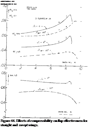
 where $2 = Jl – M2 cos2y and/v is the angle of sweep. At aspect ratios larger than 3 and below the critical Mach number, equation 55 shows good agreement with test results as illustrated on figure 55 for the variation of dCL / dot with M. When flaps are installed on such surfaces, these characteristics with Mach number of dC/d6 can also be found with equation 55 by using dCL/d6 instead of dCL /dot. As shown on figure 44, good agreement is also obtained with test and theory for the effects of compressibility on flap deflection. Since do(/dCL and d6/dCL are dependent on the same factor as a function of M, the variation of the ratio of dot /dS with Mach, number is essentially flat up to the critical, as illustrated on figure 44. Above Mcr the flap effectiveness ratio decreases in the same manner as for the two dimensional case,.
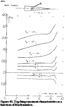
 Hinge Moment – Mach Number. The flap hinge moment coefficient variation with Mach number is given on figure 45 for a sealed flap configuration (51,g). At cx’ = 0 and low deflection angles the hinge moment coefficent is nearly constant up to Mach numbers just below the critical. At flap angles above 10 , C increases with Mach number approximately as would calculated using the Prandtl-Glauert correction. It would appear that up to the critical Mach number the section hinge moment derivative C for control devices should then be corrected in accordance with the P-G rule, thus
(56)
The above equation should hold up to the critical Mach number of the section, which will be a function of the section type and deflection angle.
Critical Mach Number. The critical Mach number of the control surface determines where the flap effectiveness becomes non-linear, as illustrated on figure 45. Thus to obtain the desired characteristics, the control surface is designed with a critical Mach number. This is done by choosing the proper sections and planforms to give the necessary high critical Mach number characteristics. As shown in Chapter VII, section camber and thickness ratio should be low for high levels of Mc r. Whereas in Chapters XV and XVII a high sweep angle and a low aspect ratio are needed to obtain a high critical Mach number
X – ROLL CONTROL


