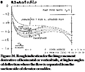
CONTROL-FLAP CHARACTERISTICS AT HIGHER DEFLECTION ANGLES
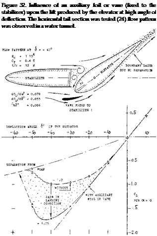
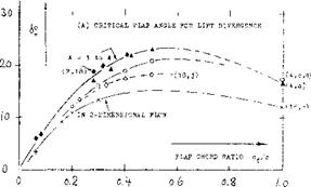
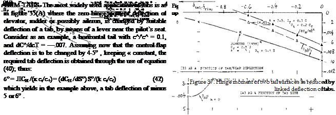
LIFT-CURVE SLOPE. At flap deflections exceeding the critical angle, a control surface still has a defined lift-curve slope, as long as the flow remains attached to the forward part of the foil section. Figure 33(A) shows that the slope is, somewhat higher than that of the surface with fully attached flow, within the range of chord ratios below 0.3. It seems that the flap has in this case, an effect similar to that of a blunt trailing edge which is known to improve lift-curve slope as well as maximum lift. At chord ratios above 0.3, the slope decreases considerably.
FLAP EFFECTIVENESS. As demonstrated in figures 1 and 18, the lift of a flap continues to increase, after passing through a more or less pronounced dip, as the deflection is increased above the critical angle. The same graphs also suggest that the lift produced by a flap, under conditions where the flow is separated from its suction side, that this lift increases very roughly in proportion to the sine of the flap angle (23). It is thus possible to approximate statistically and for practical purposes, the effectiveness of a flap above its critical angle, by the ratio
[dC^d^im^/tdC^/dfsinck] = d(sino<)/d(sin<£ ) (39)
where dCj_/d(sinoO.=. lift-curve slope of the lifting surface in plain fully-attached flow. Evaluation of experimental results, as in figure JJ(B), shows that this ratio is related to the effectiveness as in figure 2. The ratio of the two ratios, also plotted in the graph, is between 0.6 and 0.7. At chord ratios approaching zero (as in tabs» the effectiveness ratio in figure 33(B) coincides with that in
![]() THE PITCHING MOMENT due to deflection of flaps with separated suction-side flow, may also be interpolated by means of a sine function. Approximate results of this type are plotted in figure 33(C). In comparison to those in figure 4, pitching moments due to separated – flow flaps, are only 1/2 or possibly 2/3 of those in attached-flow condition. The moment obviously corresponds with the effectiveness ratio.
THE PITCHING MOMENT due to deflection of flaps with separated suction-side flow, may also be interpolated by means of a sine function. Approximate results of this type are plotted in figure 33(C). In comparison to those in figure 4, pitching moments due to separated – flow flaps, are only 1/2 or possibly 2/3 of those in attached-flow condition. The moment obviously corresponds with the effectiveness ratio.
“Tabs” are small-si2:e auxiliary flaps attached to, or part of the trailing edge of control flaps. Hinge moments can efficiently be changed by tabs.
MECHANICS OF TRAILING EDGE TABS are basically the same as those of control flaps. We thus find:
their effectiveness or influence upon lift in figure 2,
upon longitudinal or pitching moment in figure 4,
their own hinge moments in figures 7 and 8.
 |
As illustrated in figure 35, trailing-edge tabs can be used in 5 different ways, to modify the characteristics of control surfaces.
(E) INCREASING THE HINGE MOMENT
control"""*
Figure 35. Sketch showing various basic uses
of trailing-edge tabs.
![]()
 |
THE HINGE MOMENT of the tab proper will be discussed later. The influence of the tab upon the hinge moment of the control flap to which it is attached, is theoretically (30) a function of the flap-chord ratio. The influence of viscosity in combination with foil-section and flap shape, evidently obscures that of the flap-chord ratio. Results for ratios between 0.2 and 0.5 are plotted in figure 36, as a function of the tab-chord ratio. Deviation from theory is largest within the range of tab – chord ratios below 0.1. Realistic results might be approximated by
(dCH/d<*tW = "k (ct/c-f} (40)
where к = 0.05 or = 0.06 applies to smaller flap-chord ratios (in the order of 0.2) and to heavier boundary layers, and к =. 0.07 or = 0.08 to larger flap-chord ratios (in the order of 0.4) and to smooth configurations at higher Reynolds numbers. For tab-chord ratios in the order of 0.2, the variation of the flap-hinge moments due to tab deflection, is thus roughly proportional (a) to the tab angle, and (b) to the tab-chord ratio (32). Since a flap with a chord equal to that of the foil section, is simply a plain “wing” surface, the pitching moment as in figure 4, is realized to be the equivalent of a hinge – moment. Points included in figure 36, approximately agree with those obtained for conventional flap-chord ratios.
EFFECTIVENESS. To be sure, deflection of a balancing tab (in the direction opposite to that of the control flap) somewhat reduces effectiveness. When, for example, using a tab with c^ = 0.1 c^, geared so that — 6 , the reduction of dcx/d<S can readily be found from figure 2. Assuming that do^/d6 ~ (c^ or c^)/c, as it is roughly true within the range of small chord ratios, the effectiveness doc/d6, and lift per degree of deflection produced by the control flap, are reduced by ^ 10o/<? Therefore, in the example above, both tab angle and flap deflection should be made some 10% larger, in order to keep Cj_ = constant.
LINKED-TAB BALANCE. When gearing or coupling the tab in the manner as illustrated in figure 35(B) it automatically deflects (from the control-flap chord) when moving the flap, in a direction opposite to this motion. Hinge moments produced by the tab then tend to balance those of the flap. For example, for c^/c =. 0.3, the hinge moment corresponds to dCq/d6 ^ —0.008 (see figure 8). It can then be found in figure 36 that, for a coupling ratio of 6^/S = — 1, a full-span tab with c^ =, 0.13 c., will fully cancel the flap’s hinge moment. Or, when selecting a tab chord c^, = 0.1 c^ for example, or reducing the tab span to 0.10/0.13 = 0.77 times the flap span, or by reducing the coupling ratio from 1.0 to 0.77, the hinge moment will be reduced to (100—77) = 23%, in the example considered.
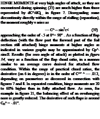
REDUCTION OF HINGE MOMENTS. Figure 37 shows hinge moments of two horizontal tail surfaces as a function of: (a) size (chord) of the linked tab; (b) deflection ratio of the linked tab. — Moments can be reduced “easily”, for example by means of a tab with c^/c^ =
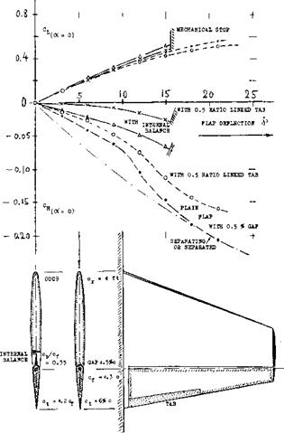
0. 1 and a deflection ratio between 0.5 and 1.0. Figure 38 demonstrates that linked-tab balance is effective, not only in the case of a plain flap, but also in combination with an internal balance. Hinge moments can thus be reduced down to a few percent of the original function. [85] [86] [87] [88]
|
Figure 38. Influence of a linked trailing-edge tab upon the lift and hinge-moment characteristics of a tail surface. |
BOOSTING HINGE MOMENTS. Full cancellation of the control moment is hardly ever desirable. In fact, there have been small and low-speed airplanes (and there seem to be some sailplanes) where stick forces in the longitudinal direction are increased by adding a tab to the elevator, geared in such a manner that it deflects in the same direction as the elevator; see part (E) of figure 35. Three things are accomplished in this way:
(a) hinge moments are suitably increased (whenever this is desirable); (b) control effectiveness is somewhat increased; (c) longitudinal stability of the airplane is improved.
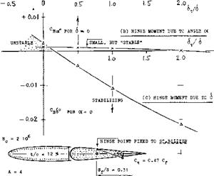
LEADING TAB. An interesting application of a linked trailing-edge tab is shown in figure 39. The elevator is basically overbalanced by means of a 50% overhanging nose. However, the tab is linked in such a manner that it deflects in the same direction as the elevator flap. The derivative is then made negative (stable):
(a) by the leading deflection of the tab, thus counterbalancing the overhang; b) to a degree by the reaction in the elevator to the tab’s hinge moment. The linkage ratio 6j./8 as recommended in the conclusion of (37) is 0.5. The mechanism described also has the advantage of providing increased effectiveness, so that a lesser deflection will be sufficient to obtain a certain lift coefficient. It can also be noted that is positive. This means that longitudinal stability of the airplane is not reduced, but slightly improved, when leaving the control stick free.
|
d#/d6 |
—■ о ________________ |
|
|
< |
э —— |
|
|
(A) EFFECTIVENESS |
||
|
dCL/doP= O.06 —(———– |
LEADING TAB ANC-L: —— ,—– 1—- 1—— 4—– |
|
Figure 39. Effectiveness and hinge moments of a horizontal (or vertical) tail surface as described in the text, loaded by a leading tab (37). |
STICK-FREE CONDITION. In a tabbed configuration where the hinge moment is reduced to nothing, the control flap will simply move to a certain limiting position (to a mechanical stop or to a point where the flow separates from the flap’s suction side). Quantitatively, combination of equations (27) and (28) indicates that
Д(dcx/dCL) = +(d<x/di ) (dCH /dCL)/(dCH /d& ) (44)
The influence of the tab upon (dC цЛіб ) corresponds to
A(dCH/d6)= (6t/8 )(dCH/d6t) (49)
where (6^/6 ) =. coupling ratio (negative) and (dC^/dd^) as in figure 36 or in equation (40). Using that equation, the reduction of the hinge moment is found to correspond to
A(dCH/d<$°) = к (St/6 ) (ct/Cf) (50)
To simplify discussion, we may also assume that the coupling ratio be 8^/8 =— 1, so that the chord ratio (Qfc/Cf) becomes the measure for the tab effect. To arrive at quantitative results, we will consider two different control-flap configurations:
(a) an aileron (or horizontal-tail) installation with:
Cf/c = 0.2; do(/d8 = 0.45; doC’dC^ = 15°
(b) a horizontal (or vertical) tail surface with:
cf/c = 0.4; da/d6 =» 0.70; do(/dCL = 20°
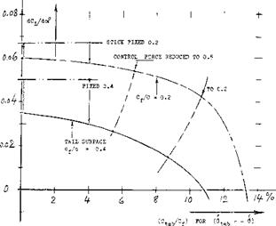
where (dot/dC^) is meant to be for fixed-control condition. Using equations (49) and (50) in conjunction with values taken from the various graphs, stick-free lift curve slopes have been computed for the two cases. Figure 40 presents these values as a function of the tab size. The loss of stabilization can be considerable, particularly in the tail surface considered.
|
Figure 40. The stick-free stabilizing effect of (a) an “aileron” section with c^/c — 0.2 (b) a tail surface with c^/c — 0.4 computed as explained in the text. |
|
0.0(o I I ‘ I I
Figure 41. The stick-free stabilizing effect of tab-balanced control surfaces as a function of the flap-chord ratio. |
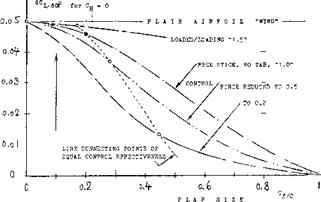
FLAP SIZE. The most important parameter affecting stabilization is the chord ratio of the control flap. Using the same functions as above, we have computed the stick-free lift-curve slope of a horizontal (or vertical) tail surface similar to that in case (b) above, but with varying flap-chord ratio. Figure 41 shows the lift-curve slope, as a function of the chord ratio, with balancing trailing-edge tab, geared at a ratio so that the hinge moments are reduced to 1/2 and to 1/5, respectively. The loss of stick-free stabilization is again seen to be very considerable. Of course, small flaps may not be sufficient in regard to the maximum lifting or compensating effect they are expected or required to produce. Unfortunately, the stabilizing effect of tabbed tail surfaces reduces more and more as the flap-chord ratio is increased. In addition, it should be realized that reduction of “hinge moments” to 1/2 or to 1/5 as assumed, is not really proper. These moments grow in proportion to the square of the flap chord. Accordingly, a small flap might not need any balance at all, while it might be desirable or necessary to reduce the torque of a larger flap, not just to 1/5, but possibly to 1/10. A line connecting points of equal hinge moments (equal in feet-pounds) is shown in figure 41, thus demonstrating the fact that the stabilizing effect of geared-tab control surfaces reduces very strongly, after exceeding a certain range of small flap-chord ratios.
SERVO CONTROL. Deflection of a tab (rather than of the flap itself) by means of some small control force as in figure 35(C) can be utilized to move larger-size control flaps (elevators, rudders, ailerons). This type of servo system has been tried on ship rudders, in an effort to reduce the heavy steering machinery usually required (39). In airplanes, the servo-tab system has been used in a number of larger airplanes (40) to operate the rudder. The straight-forward system has a number of drawbacks, however: (a) it will not work at higher deflection angles because of flow separation; (b) it may
fail at low speeds where mecnanical friction will interfere; (c) it will reduce stick-free stabilization considerably (36); (d) the doubly-linked system can invite flutter trouble (44); (e) there is a time lag involved in the operation (41,b). — Regarding the last point, dynamic behavior (45) is as follows. After sudden deflection of the tab, the flap assumes the proper position almost aperi – odically, but after a delay in the order of 1 second (as tested on a larger than full-scale model). The delay is proportional to V I/q, where I = mass moment of inertia and q = dynamic pressure. When suddenly releasing tab and flap, both components oscillate several times, before coming to rest in the balanced position. — Nevertheless, the aerodynamic mechanism of servo-tab control deserves to be presented.
REDUCTION OF TORQUE. A servo-tab system can be considered to be a type of fluid-dynamic balance. The tab deflection required to move a control flap (within the linear range of their characteristics, and at Cj_ =. constant » zero) is found from equating their hinge moments:
(dCH/d6 )$ ^-(dCH/d6t (52)
For assumed chord ratios of c^/c = 0.4 and c^/c*. =. 0.2, for example, the deflection-angle ratio would be
<^/<S = —(dC^ /d6 )/(dC ц /d<^ ) ^ —0.5 (53)
where the moment due to tab deflection is obtained from equation (40) for c^/c ^ 0.2 (0.4) = .0 8. The control moment (at the stick) required to deflect the tab, in comparison to that of the control flap without any balance, approximately corresponds to
(servotab)/(plainflap) = —(6^/6 )(c^/c^f (54)
which is equal to 2% in the example considered. Theoretical possibilities of this system thus appear to be great (41). [89] [90] [91] [92] [93] [94]
|
and as calculated (see text). |
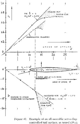
FULLY-MOVABLE TAIL. Figure 42 shows characteristics of a fully movable servo-tab operated tail surface. We want to determine the control forces required. Since there is no fixed part (fin or stabilizer) we can consider the hinge moment of the surface either as that of a flapped section with c^/c — 1.0, or as longitudinal (pitching) moment of that section. To keep the notation as in control flaps, use of figures 7 and 8, at c^/c = 1 is recommended. A simplified analysis is possible, however, through consideration of the location along the chord: (a) of the lift due to angle of attack; (b) of the additional (negative) lift due to deflection of flap or tab ( whatever name we want to give in this case). — The component under
(a) was experimentally (38,c) found to be at ^ 0.225 of the chord. For the hinge location at 0.15 c (see subscript “x”) the moment arm of (a) is then 0.225 — 0.15 =. 0.075; and the hinge moment of the plain foil corresponds to dCm)C/dC^Q = — 0.075. When using the servo flap (or tab) to deflect the surface as a whole, the longitudinal moment due to lift must obviously be cancelled by that due to deflection of the flap. In order to obtain the same lift coefficient, o< has to
be somewhat larger, however, than in the plain foil; the ratio of the angle is
(c^+Ac*)/c* = 1 —(dcx/d<S ){h/o()
which is 1.26 for the configuration considered. In a simplified analysis, we will assume that the lift differential produced by the flap has its center of pressure at 0.5 chord (as explained in connection with figure 6). The moment arm of the due-to-flap force is then Ax/c = ACm/ACL = 0.50 – 0.15 – 0.35, in the case considered. Since AC^/C^ = (1/1.26) —1 = —0.21, the hinge moment due to flap – or tab deflection is
dCm*/dCL = dCH/dCL= +0.35 0.21 = +0.074 (56)
This value is sufficiently close to that as tested. The results in figure 42 have thus been checked by analysis.
TAB-HINGE MOMENTS (at the tab’s hinge line) are usually very small; see figures 7 and 8 at cp/c below 5°/<? and consider moment proportional to c£ . Considering the servo-control flap as in figure 42, its torque can be determined through the use of equation (40). As a function of C^, the flap’s or tab’s resultant hinge moment corresponds to
(dCH /dCL )t = (dCH /dCL) + (dCH /d6 )t/(dC,_ /dA
where (dC|_/dd ) to be computed, or equal to 0.013 as tested for the configuration in figure 42. Using values picked from figures 7 and 8, the variation of the tab hinge moment is found to be
(dCH /dCJ ^ 0 + 0.008/0.013 = 0.6 (58)
This derivative is based upon flap or tab chord. In order to make a comparison with the hinge moment of the plain foil, the result must be multiplied with (c^/c) = 1/100. The tab-moment derivative, referred to total foil chord, is thus 0.006, which is some 8% of that of the plain foil balanced at 0.15 of its chord. Considering the tab deflection required, corresponding to 6^/6 = — 0.87, the control moment (in the steering column) required for servo-tab operation, will only be
0. 87 (0.08) 7% of that required to move the unbal
anced control surface to the same lift coefficient.
BALANCE OF TAB TORQUE. Boundary layer thickness reduces the tab effectiveness. Gaps around the tab’s hinge axis are also undesirable. As far as hinge moments (around the same axis) are concerned, reference (30,h) demonstrates that an overhanging-nose type of balance can be very effective, in a manner and to a degree similar to what is explained in a previous section on this subject.
LINKED SERVO SYSTEM. As stated in the beginning, simple servo-tab control has serious operational disadvantages. In fact, this svstem is no longer used. Control characteristics were substantially improved, however, by suitable mechanical coupling between flap and tab. One such system is illustrated in figure 35(D). Because of the lever linking (but not connecting) the actuating rod with the flap’s hinge point, a certain moment can be transferred to the flap and not only to the tab. The mechanism can be understood by considering limiting conditions: (a) when keeping the flap fixed, the control rod causes a deflection of the tab; (b) when keeping the tab fixed (against the flap), the control rod causes directly a deflection of the flap. — The control force of the linked servo system corresponds to the total derivative
dCH (dCH /dA )l +(dCL /d6 )(dCH /dCL)0
d£ l-[K(cf/ct)2(b/bt)(dCH/d<g )/(dCri/dd)t]
where bt/b = tab-span ratio (which might be less than unity and К mechanical coupling ratio between tab and flap in stick-fixed condition. This ratio К = di/d^ is negative, К ж –0.5 in the configuration as in figure 35(D). Selecting average values for the derivatives to be used in the equation, that configuration is expected to operate at a control force which is only 1% of that of the same flap without balance
SPRING-TAB CONTROL. The servo-tab system in figure 35(C), is based upon aerodynamic forces and thus dependent upon dynamic pressure and flying speed. Replacing the actuating element in that system by a mechancial spring and providing suitable stops, servo operation begins after exceeding a minimum hinge moment (in feet-pounds) and it terminates upon reaching a certain control force (in pounds) corresponding to loading and elastic constant of the spring element used. Such a system is as in figure 35(D). When moving the control stick, the tab is deflected first (compressing the spring element), thus causing the desired deflection of the flap in a manner similar to that of a simple servo – tab system. Upon reaching a certain limiting torque, either because of high dynamic pressure or at larger angles of deflection (when flying at lower speeds), the control lever goes against a stop; and the flap is then directly controlled by rod and stick. The theory of this system has been worked out (49); considerable experimentation is reported (50). Advantages are as follows:
(a) Stick-free stability is not affected, particularly when the spring-tab system is preloaded, (b) Time lag and “sloppy” performance are eliminated, (c) Overcontrolling (due to small control forces) is prevented, (d) In high-speed pull-out maneuvers, stick force is (or can be made) proportional to acceleration, (e) Whenever necessary, the control flap can be moved to high angles of deflection (such as during the landing maneuver).
 CONTROL FORCES. As far as control moments are concerned, it may be assumed that tab torque ^ (ёСц/ёб)^, while disregarding the influence of cX or C^ and 6. The contribution from the direct displacement of the flap against the spring element, is proportional to the spring constant. For an extremely weak spring, we obtain the small control forces as discussed above for the “linked” servo system. For an extremely stiff spring, the control moment is equal to that of the flap without tab assistance. With the control lever against one of the stops and the tab in the corresponding end position, the hinge moment is that of the flap without balance, minus a differential corresponding to the final tab deflection. Various modifications of the system are possible. Examples for stick forces obtained through such arrangements are presented near the end of the “aileron” chapter.
|
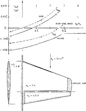
Figure 30. Exposed horns as tested by NACA (22,c) on two different foil-section shapes. |
|
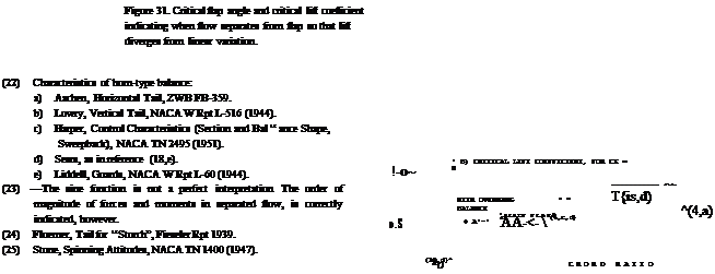
At an angle of deflection, say between 10 and 20° , the flow usually separates from the suction side of trailing – edge flaps. On the other hand, all control flaps used in conventional airplanes, are usually designed so that they may be deflected to angles, say between 25 and possibly above 30 . Characteristics at such high angles are as described in the following section. THE CRITICAL FLAP ANGLE, where the lift produced by deflection starts to deviate from the linear variation, as for example in figure 1 or 18, is a function of section shape, type of balance, angle of attack, aspect ratio, of other geometrical parameters as well as of the viscous conditions of the fluid flow. Figure 31 presents critical flap angles, for zero angle of attack, as a function of the flap-chord ratio: The critical angle and the corresponding lift coefficient increase with the chord ratio; and they reduce to nothing as the flap chord is decreased to zero. The angle reaches a maximum (indicating optimum section camber due to flap deflection) at Of/c somewhat above 0.5. — The critical lift coefficient is comparatively independent of the aspect ratio. Depending upon section shape, maximum lift coefficients obtained through flap deflection, at zero angle of attack, are between 0.8 and 1.2. |
|
o>2- о A |
