INFLUENCE OF FLAP-SECTION SHAPE
As explained before, foil section thickness has an influence upon control-flap characteristics. It has been discovered, however, that the angle at the trailing edge, included by upper and lower flap side, and other variations of flap-section shape are more directly responsible for such effects than the foil thickness ratio. Various shape parameters are discussed in this section.
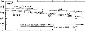
SECTION THICKNESS. The control derivatives of a flapped and tabbed 0015 foil section are presented in figure 12. In comparison to other sections with thickness ratios between 9 and 12%, the following conclusions can be dfawn:
(a) The lift-curve slope is reduced, corresponding to section thickness ratio. The influence of a 0.5% hinge gap on dCL/do( is noticeable.
(b) In sealed condition, the effectiveness ratios do</d<S, both of flap and tab, are “normal”. The influence of a hinge gap is considerable.
|
FLAP CHARACTERISTICS : lo<./d^ = 0.46 (0.5S ) dCm{dCL = +.020 (+.020) dC^d*0 = -.0075 (-.008) dCH//dCL = "•°25 C"-02*) dCg/doP = -.oo23 (-.0022 dCg=dS° = -.0063 (-.008) ГАВ CHARACTERISTICS : dof/dSt = 0.21 dCH/d^t = -*010 dCH/d^t = -*°°5 FLAP AND TAB NEUTRAL : dCj/doP = 0.089 (0.096) STICK-FREE (TAB NEUTRAL) : dCj/doP = 0.075 (0.080) VALUES IN PARENTHESES ARE FOR SEALED FLAP GAP |
(c) 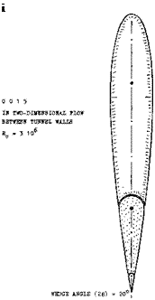 The dCm/dS derivative fits into the pattern as in figure 4.
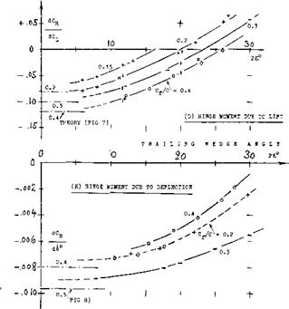
(d) The value of dC^j /dC(_ is low (see figure 7). This is evidently a true thickness and/or trailing-wedge effect.
(e) The values of dC^/d6 , for flap and for the tab, are average (see figure 8). With open hinge gap, the flap moment is noticeably reduced.
(f) The value of the stick-free lift-curve slope is comparatively high, evidently because of the derivative as under (d).
All in all, characteristics of this 15^ thick section are thus not too much different from those of sections with smaller thickness ratios, although flow pattern, forces and moments are evidently somewhat more sensitive as to hinge-gap interference.

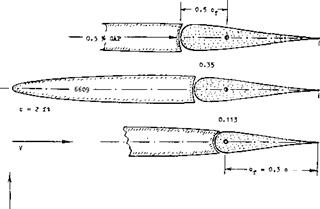
TRAILING-WEDGE ANGLE. Modern laminar-type and high-speed foil sections have (if with “true” 6-Series contour) a hollow (cusped) afterbody shape. Their trailing-wedge angles are, as a consequence, smaller than those of other, more conventional sections. One and the same trailing-wedge angle can thus be connected either with a bulging or a hollow flap shape. Figure 13 shows three different ways of changing the shape of a control flap together with that of the foil section: [81] [82] [83] [84]
Figure 12. Control characteristics of a configuration based on 0015 foil section, tested (15,f) in two-dimensional flow.
(a) When changing the section thickness ratio, the flap shape (thickness) varies accordingly.
(b) A similar variation is obtained when shifting the position of maximum section thickness along the foil chord, back or forth.
(c) As mentioned above, certain foil sections have a cusped (hollow or concave) shape in that portion of the chord where flaps might be installed. For example, a 63-010′ section (in its original and true form) Avill thus result in a flap shape considerably different from that in a 0010 section.
|
|
|
TRAILING – WEDGE ANGLE |
|
(A) SECTION THICKNESS |
|
(B) LOCATION OF MAXIMUM THICKNESS |
(C) AFTERBODY SHAPE
|
|||||||||
|
|||||||||
|
|||||||||
|
|||||||||
|
|||||||||
|
|||||||||
|
|||||||||
|
|||||||||
|
|||||||||
|
|||||||||
|
|||||||||
|
|||||||||
|


![]()

![]()
![]()
![]()
![]()
![]()
sufficient thickness ratio, the tangential components of the pressure forces do produce a hinge-moment component. Positive pressure forces on the pressure side, and negative ones on the suction side, form together a force couple, the direction of which is such that it tends to move the flap against the oncoming flow.
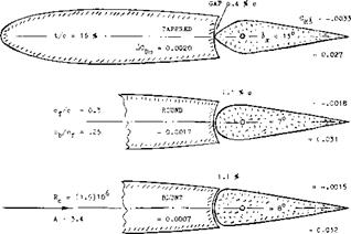
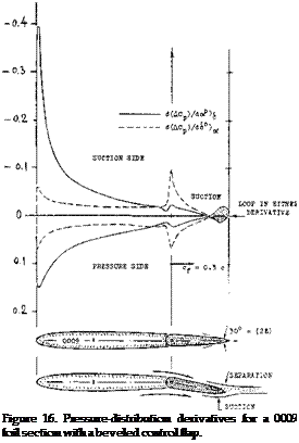
(b) Tested pressure-distributions due to angle of attack and due to flap deflection (17), are plotted in figure 16 for a beveled flap shape. The two derivatives show practically identical loops near the trailing edge; and these loops, representing “negative” hinge-moment components, are obviously responsible for much or most Ы the reduction (and possibly reversal) of the hinge moments evident in figure 13.
THE FLOW PATTERN connected with any pressure – distribution loop of the type as in figure 15, is most likely as follows:
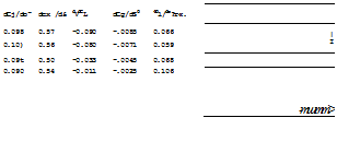
BEVELED TRAILING EDGES. Since flap shape, as described above, considerably affects hinge moments, suitable variations may be used to change the level of these moments. It can be convenient, for example, in a finished airplane, to exchange an elevator or rudder with a somewhat differently shaped design. Figure 15 illustrates several possible modifications of a flap; consequences are tabulated. We can see that neither thickening the trailing edge, nor rounding of that edge (with a comparatively small radius) has much of an effect upon hinge moments (although the parasitic drag is increased). However, curvature in form of an elliptical contour, or beveling of the thickened trailing edge (to an enclosed angle of 20 or 30° ) reduces the hinge-moment derivatives considerably. This type of beveling (necessarily combined with increased flap thickness) is obviously a form similar to convex (bulging) flap shape, id est with the location of curvature far aft.
PRESSURE DISTRIBUTION. Hinge moments are the result of pressure distributions; and those distributions evidently change appreciably, not just in size but also in character, as thickness ratio, trailing-wedge angle or flap curvature are varied. Explanation of reduced and reversed hinge moments is possible by considering two components:
(a) Pressure forces on the 1/2 cylindrical forward edge of the flap cannot produce any hinge moment; and those along the flanks could not either in a really thin flap (id est a flat plate). However, in a flap with
116) As a function of the angle of attack, the consequence of separation from a trailing wedge can be such that a reversal of the lift-curve slope takes place; see the chapter on “airfoil sections”.
(17) Within a limited range of the angles involved, the pressure distribution varies in linear proportion to them. The pressure coefficients can thus be presented
(a) On the suction side of convex (bulging) or beveled flaps, boundary layer material tends to accumulate “at” the trailing edge. With or without local separation of the flow, the pressure, therefore, discontinues to rise to a positive value at the trailing edge.
(b) On the pressure side, the pressure gradient is essentially negative. Boundary layer growth (and separation) are thus prevented; and the flow follows the curvature of the flap surface. Negative pressures (suction) may thus develop as shown.
in form of derivatives, as in figure 16.
The flow from the upper and that from the lower side of the flap, join each other at or beyond the trailing edge at one and the same pressure level (near zero). A loop is formed in the pressure distribution, accordingly. It
can also be said that the flow pattern described is similar 7. OVERHANGING-NOSE BALANCE to an imaginary one in which the rear stagnation point is shifted around the trailing edge, onto the suction side.
FLAP CAMBER (a one-sided curvature in the flanks of a flap) is usually found only in ailerons, and is as such discussed in the chapter on this subject. Camber in the magnitude of 1% of the flap chord, produces a differential ДСц « 0.024, in the direction to the convex side. Here as in all other cases of flap-section curvature the convex side is obviously subjected to a component of suction, while a hollow flap side encounters increased pressure.
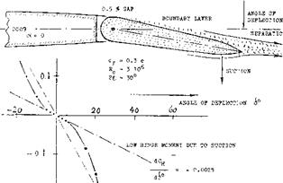
“S” TYPE MOMENTS. Beveling of thickened flaps is described above and presented in figure 15, for example, as a means of reducing hinge moments. Figure 17 demonstrates, however, that such reduction has limitations. The low hinge-moment derivative Сц£ = — 0.0025 is restricted (in that particular example) to a narrow “c” range of less than plus or minus 5° . The amounts of suction which the lower side of the beveled portion of the flap can gain, and which the upper side can lose, are evidently reducing as the flap angle is increased. Beyond plus and minus 20° , the hinge moment approaches values corresponding to = — 0.0090 which is about the level for a plain flap (see figure 8). Beveling of the type as in figure 16, obviously reduces hinge moments where they are small; and it does not materially reduce them where they are large. The “S” shape of the hinge-moment function is not desirable.
|
0.2 |
All hinge moments presented so far, are those of “plain” flaps. Elevators, rudders and ailerons of this type can be used in small and low-speed airplanes, where hinge moments or forces do not exceed a magnitude which the pilot can apply with his hands to the control stick. In larger sizes (and at higher speeds) some type of aerodynamic balance designed into the control flaps is desirable or necessary: to reduce the pilot’s efforts and to prevent fatigue, to make the airplane more maneuver – able, to reduce structural strain in flaps and control linkages. The most frequently used type of balance is by means of an overhanging nose (leading edge) added to the control flap.
DEFINITIONS. When deflecting a control flap, static pressure increases on one side, and a certain negative pressure arises on the other side. Upon adding an overhanging “nose” to the control flap (or by moving the hinge axis back) some aerodynamic balance of forces normal to the flap chord can thus be expected. Since the control effect depends upon the chord “c_p”. The length of the flap nose (cb, with “b” from balance) is defined forward from the hinge axis. This length may be expressed as a fraction, either of the total flap chord or of the chord “cp”. We have selected to use the latter definition.
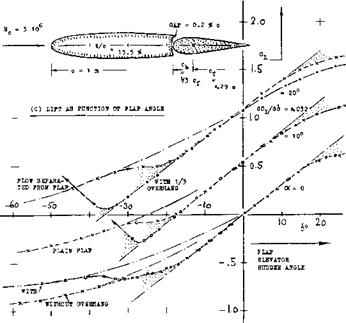
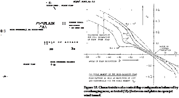
EXAMPLfe. Experimental characteristics of a control surface configuration balanced by an overhanging nose, are presented in figure 18. The variation of lift as a function of flap deflection and of angle of attack, is of the same type as described in connection with figure 1. Part (C) of figure 18 shows, however, that lift is reduced on account of nose balance, at higher angles of attack (such as 20° ) and at larger deflections (above 30° under the conditions as tested). As far as flap effectiveness is concerned, the ratio dcX^d6 corresponds to the statistical function as in figure 2. Comparison with other data (see later) indicates that the hinge moment as in part (D) of the illustration, is appreciably reduced as against that
![]()
![]()

зев FIGURE 8
+
Figure 17. Characteristics of a control flap with beveled trailing edge, tested (15,a) under two-dimensional conditions.
![]() of the same flap with only a nose corresponding to the radius around the hinge axis. The same graph also demonstrates:
of the same flap with only a nose corresponding to the radius around the hinge axis. The same graph also demonstrates:
(a) that the constant portion of hinge moment slope CH£ is practically the same for the angles of attack tested (between-10° and 4-20° .)
(b) that the range of deflection angles within which
the slope is really constant, is limited (be
tween plus and minus 10 or possibly 20° , under the conditions as tested).
It should be kept in mind that the hinge-moment derivatives as presented in the following paragraphs and illustrations, are only those corresponding to the linear variation as noted in part (D) of figure 18. For hinge moments at higher angles of deflection and/or attack, see the next section.
2.0-
 (A) LIFT A3 FUNCTION 0? ANGLE 0? ATTACK £ = 0
![]()
|
(B) STICK-FREE FLAP DEFLECTION SO THAT HINGE MOMENT * ZERO |
![]()
(18) Investigation of overhanging-nose balances:
a) Gorski, САНІ (Moscow) (1930); see (4,a).
b) Goett, Elevator Shape, NACA T Rpt 675 (1939).
c) Junkers W’Tunnel Results D-7182/91 (1942)
d) Harper, Aerodynamic Balance, NACA T’N 2495,
e) Sears, Control Surfaces, NACA WR L-663 (1943).
f) Purser, Correlation, NACA W Rpt L-665 (1944).
g) Bates, Tail Surfaces, NACA TN 1291 (1947).
h) Smith, Elevators, NACA T Rpt 278 (1927).
i) Bradfield, Controls, ARC RM 1420 (1931).
j) Dirksen, Tails, ZWB 359 (1935); see (4,d).
k) Adamson, Nose and Gap, ARC RM 2326 (1940).
m) Riebe, 0009 Various, NACA WR L-196 (1945).
n) Tamburello, Tail, NACA W Rpt L-41 (1946).
o) Hoggard, Flaps, NACA TN 1248 (1947).
(19) Kirste, Trav Cercle Etudes Aerot Vol 7 (1932).
OVERHANG LENGTH. Considering the effective length of the overhanging flap nose, finite thickness of foil section and flap have to be taken into account. A “plain” flap has usually a half-round nose corresponding to foil-section thickness at the hinge axis. All pressure forces on this half-circular shape are directed toward the hinge axis. As mentioned before, they can thus not contribute to balance; the corresponding nose length is ineffective. Depending upon section thickness (at the location of the hinge) and flap chord, this length can be between 5 and 20% of the chord c^. Upon increasing the nose length beyond this lower limit, the magnitude of the hinge-moment derivatives reduces steadily, such as illustrated in figure 19.
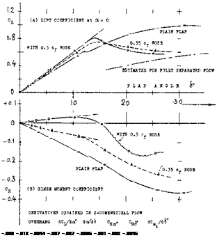
LIFTING CHARACTERISTICS. The results tabulated in figure 19, show that the lift-curve slope dC^/dcx is reduced when adding an overhanging nose, evidently because of the surface discontinuity (gap) necessitated. The flap effectiveness ratio do(/d6 is, on the other hand, increased so that the lift curve slope due to flap deflection dCj_/d<£ is seen to be increased, a few percent. In other words, within the range of small and moderate angles of deflection, a well-rounded flap nose usually improves the flow past the suction side, around the bend produced by flap deflection.
|
Figure 19. Example of a control surface tested (18,n) under two-dimensional conditions of flow, with three different degrees of overhang – balance, at zero angle of attack. |
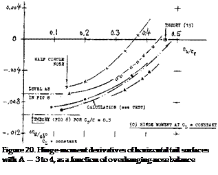
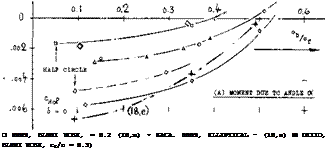
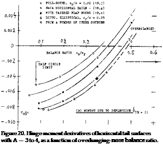
HINGE MOMENTS. Three different hinge-moment derivatives are plotted in figure 20 as a function of the nose-balance length ratio cb/c^. The derivative due to angle of attack (id est, due to lift) as in part (A) reduces, slowly at first, with the nose length ratio; and it reaches zero at length ratios between 40 and 50°/°. The moment due to deflection is usually more important than that due to lift. Part (C) of the graph demonstrates how dC^/d6 reduces as the length of the balancing elevator – or rudder nose is increased. Assuming that the pressure or normal-force distribution along the flap chord be triangular (reducing to zero at the trailing edge) we may qualitatively compute the hinge moment and its variation due to adding a nose portion. This was done, taking into account that the first piece of overhang, assumed to be 12.5#> of the aft-of-hingc-axis flap chord, would be ineffective (see above). The semi-theoretical function, included in graph (C), confirms the general character of the experimental lines.
CHARACTERISTICS AT CX = ZERO. So far, all control-flap characteristics have been considered within the non-dimensional system of partial derivatives. Normal forces and hinge moments at constant angle of attack can directly be of interest, however: (a) in the beginning on an airplane maneuver, when suddenly deflecting a control flap, (b) in wind-tunnel testing, where investigation at zero angle of attack is comparatively simple. — For ex’ = zero, the complete hinge-moment derivative is
CHi = (dCH /dS k+tdCH /dCL)<5(dCL/doc)(do9a6 )
 |
|
Because of the slope dC^/doC, the aspect ratio and other conditions affecting lift (such as those of a wind tunnel) have considerable influence upon the derivative; see (8).
NOSE SHAPE. Results of systematic flap or nose-shape investigations are plotted in figure 21. Principle results are as follows:
(a) Considering hinge moment as a function of deflec
tion, the partial derivative dC^/dCj_ (as in part ‘A’ of figure 20) is of lesser importance. The complete derivative, id est at eg — zero, there
fore, provides quick comparison between different shapes, types of balance, and flap-chord ratios — provided that aspect ratio and test conditions are kept constant.
(b) As far as lift is concerned, it can be stated that the slope dC_/d& is on the average not affected by overhanging-nose balance. Depending upon nose shape, the flow around the bend at the suction side, toward the flap, may be somewhat improved or somewhat obstructed, however, in comparison to that past a plain flap. As a consequence C^(6) is not always a straight line.
(c) 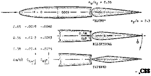
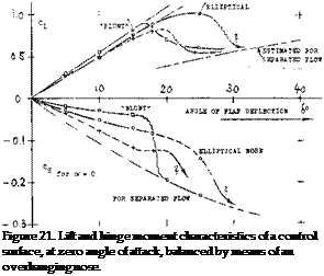 The maximum lifting effect (C^mx at eg =- 0) is also a function of nose shape.
(d) Tapered nose shapes (giving the flap a more or less sharp leading edge) do not readily come in contact with the outside flow. Their balancing effect corresponds to the local pressure differential between upper and lower side of wing or tail surface.
(e) Well rounded and “full” nose shapes “emerge” on one side from the contour of the foil section. Strong suction forces develop, as a consequence, reducing the hinge moment appreciably.
The suction forces arising on the emerging side of an overhanging nose provide an important fraction of the balancing effect; and it is this influence which causes much of the wide spread in the results as plotted in part (B) of figure 20. Depending upon shape, length, and deflection, the flap nose can also facilitate the flow past the bend in the suction side, so that d€^ /db slopes and maximum lift coefficients may be obtained which are higher than those due to same-size plain flaps. This applies to roughly 1/2 elliptical nose shapes. On the other hand, conditions around the bend can also be such that flow separation takes place suddenly, accompanied by a drop of the lift coefficient to a comparatively low’ level. Such termination of effectiveness is seen, for example in figure 21, beyond the deflection angle where the highly tapered nose comes out of the suction-side contour.
 HINGE GAPS. Every control flap requires some clearance to permit: motion free of mechanical friction. We will assume that the width of the gap between flap nose and the fixed part of wing or tail surface of an airplane, may be in the order of 1/4 inch, or 1 cm. Measured as a fraction of total full-scale chord, the gap may then have a width “s” between 0.3 and 0.6o/° of that chord. Aerodynamic consequences of hinge gaps are:
|
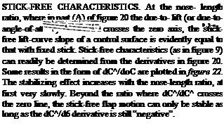
THE INFLUENCE UPON LIFT is twofold. Figure 23 shows that (dC^/dc*) as well as flap effectiveness doCd6 decreases steadily when opening up the hinge gap. This means that the lifting effect dC^/d6 may be reduced between 17 and 32°/° for the rather extreme gap size of 1% of foil chord. The influence upon lift of the comparatively large openings (voids) connected with overhanging-nose balance, can also be found in the tabulation in figure 19. The lift-curve slope decreases uniformly with the size of an open overhang balance. A certain interaction must be expected between nose size and/or shape and the size of the control gap. Figure 24 demonstrates that the influence of a plain control gap upon the lift-curve slope is also a function of location or of flap-chord ratio. |
 |
![]()

![]()
![]()
 a reduction of lift-curve slope, a reduction of flap effectiveness, an influence upon hinge moments.
 |
![]()
![]()
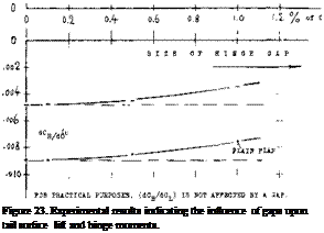
 COVERED BALANCE. Figure 23 shows a small influence of presence and size of gaps upon the hinge moment due to lift. The openings (gaps) necessarily connected with the open overhanging-nose type of balance, increase the parasitic drag of a tail surface, possibly by 10°’/o. One has, therefore, tried to cover the openings, for example as in the last configuration in figure 26. It is readily understood that lifting, drag-, and pitching-moment characteristics of such configurations will be essentially the same as those of and due to plain flaps. Of course, the effectiveness (lift) of such “internal” balances is necessarily limited (for example, by a maximum deflection angle of 16° , instead of 25 or 30° ); see figure 25.
|
|
|
|
|
iCDfi = INCREMENT Of SECTION DRAG DUE TO CONTROL HINGE GAPS |
|
LIMIT FOR LINEAR HINGE MOMENT VARIATION |
|
Figure 25. Characteristics of an elevator flap, tested (18,k) with 4 different shapes of a 25% overhanging nose balance. |
(20) Characteristics of internal balance:
a) See references (18,d) (18,e) (18,k).
b) Braslow, Internal, NACA TN 1048 (1946).
c) Pressure distribution derivatives see (18,m).
d) Denaci, Internal, NACA W Rpt L-432 (1943).
(21) The internal balancing nose plate can also be displaced to one side, thus permitting deflection, for example, between 4- 10 and —20°
PRESSURE DIFFERENTIAL. Balancing forces correspond to the pressure differential between upper and lower section side, in the small gaps at the ends of the cover plates. As derived from basic foil-section and flap theory, this differential is roughly expected to be of the form:
Дср = tydCL/doOcx + k2(dCL/dcS )t5 (38)
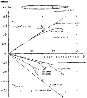
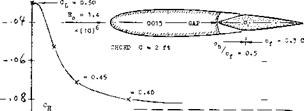
where dC^/d6 .= (dC|_/doO(do{/di) and where k, and k2 are constants depending upon section shape and the location of the gaps, approximately defined by c^/c. Evaluation of tested values (20.b) indicates, for example, that for cp/c = 0.2, the constants are in the order of kj = 0.40 and k2 between 0.10 and 0.15. Figure 27 demonstrated, however, that the pressure differential between the covered sides of the nose decreases rapidly, when introducing the gap required to permit free motion of the flap. Leakage across the nose gap may be prevented by means of a suitable seal, such as in figure 26.
|
/.1 * of C 4- |
![]()
![]()
![]()
 o. H – e.£ o. t io
COVER PLATES. As described in (20,d) characteristics of an internal-type balance can also be influenced by bending the cover plates:
(a) when bending them out of the true section contour, the magnitude of the moments due to deflection reduce within limits.
(b) by bending the plates to within the section contour, the value of the moment due to deflection increases somewhat.
(c) in either case, the hinge moment due to lift (or angle of attack) changes in the direction opposite to that of the moment above.
The local pressure at and directly aft of the edge of each plate is evidently responsible for these effects.
INTERNAL EFFICIENCY. Figure 26 proves that internal balance can reduce hinge moments. Of course, the balancing effect also corresponds to the length of the plate ahead of the flap; and that length is restricted through the geometry within the covered space (21), Even disregarding this restriction, the graph demonstrates that an internal balance is somewhat less efficient than a comparable well-shaped open overhanging – nose. balance. The advantage of the internal type of balance is thus found in the reduction of drag as stated above.
|
|
|
Figure 28. Lift and hinge moment of vertical (or 1/2 horizontal) tail surface tested (22,b) with and without horn balance. |
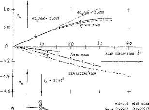
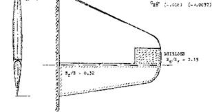
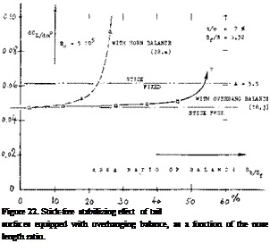
THE HORN-TYPE BALANCE, as for example in figure 28, could be considered to be a part-span overhanging – nose type. Such horns are located at the outer ends of tail surfaces. Lift and hinge moment show the familiar behavior, first a linear range of variation, as a function of flap deflection, and then a transition to a higher slope, due to flow separation from the suction side of the flap. The balancing effect is, of course, a function of chord – wise and spanwise dimensions of the horn. The simplest method of defining horn size, is the area ratio S^/S where Sj-j area of the horn, measured ahead of the hinge axis, thus including a part of the radius-type nose which every plain flap usually has.
|
(or vertical) tail surfaces. |
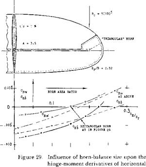
THE HINGE-MOMENT derivative CHo( and the total derivative Сц£ of two horn-balanced tail surfaces are plotted in figure 29, as a function of the horn-area ratio. C^ reaches first and crosses the zero line, in a manner similar to that of the overhanging-nose type balance in figure 20. There are some differences, according to shape and arrangement of horns:
a) The two configurations, tested with “shielded” horns (figure, 28 and 29) show approximately the same slope of balance versus area ratio.
b) Exposed horns (as in figure 30) evidently have the strongest effect of reducing hinge moments, particularly in regard to.
c) Depending upon shape and location of the horn,
can be made zero by an area ratio between 18 and 28%.
If in view of maneuverability, a positive (stabilizing) C ^derivative is undesirable; A shielded horn type may therefore, be used to advantage.
|
|
|
|


