Relationship between spanwlse loading and trailing vorticity
It is shown below in Section 5.5.1 how to calculate the velocity induced by the elements of the vortex sheet that notionally replace the wing. This is an essential step in the development of a general wing theory. Initially, the general case is considered. Then it is shown how the general case can be very considerably simplified in the special case of wings of high aspect ratio. The general case is then dropped, to be taken up again in Section 5.8, and the assumption of large aspect ratio is made for Section 5.6 and the remainder of the present section. Accordingly, some readers may wish to pass over the material immediately below and go directly to the alternative derivation of Eqn (5.32) given at the end of the present section.
5.5.1 Induced velocity (downwash)
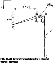
Suppose that it is required to calculate the velocity induced at the point P(x, Z|) in the у = 0 plane by the L-shaped vortex element associated with the element of wing surface located at point P (.v, z) now relabelled A (Fig. 5.25).
W, S/t S*1
|
4tt(x — *i) |

Making use of Eqn (5.9) it can be seen that this induced velocity is perpendicular to the у = 0 plane and can be written as
From the geometry of Fig. 5.25 the various trigonometric expressions in Eqn (5.26) can be written as
![]()
![]() z — Z
z — Z
J(x – Xi)2 + (z – Zi)2 X — XI
]{x~ Xi)2 + (z + Sz – Zj)2
/„ 7T . . z + Sz — z і
cos(02 + x) – Sin 02 = ■
y(x – Xi)2 + (z + Sz – Zi)2
The binomial expansion, i. e.
(a + b)n = d1 + ruf~lb + • • can be used to expand some of the terms, for example
where r = y{x — jq)2 + (z — zi)2. In this way, the trigonometric expressions given above can be rewritten as
Equations (5.27 to 5.29) are now substituted into Eqn (5.26), and terms involving (Sz)2 and higher powers are ignored, to give
In order to obtain the velocity induced at Pi due to all the horseshoe vortex elements, Svt is integrated over the entire wing surface projected on to the (x, z) plane. Thus using Eqn (5.30) leads to
![]() , , 1 Ґ fx’+c dk
, , 1 Ґ fx’+c dk
The induced velocity at the wing itself and in its wake is usually in a downwards direction and accordingly, is often called the downwash, w, so that w = —v;.
It would be a difficult and involved process to develop wing theory based on Eqn (5.31) in its present general form. Nowadays, similar vortex-sheet models are used by the panel methods, described in Section 5.8, to provide computationally based models of the flow around a wing, or an entire aircraft. Accordingly, a discussion of the theoretical difficulties involved in using vortex sheets to model wing flows will be postponed to Section 5.8. The remainder of the present section and Section 5.6 is devoted solely to the special case of unswept wings having high aspect ratio. This is by no means unrealistically restrictive, since aerodynamic considerations tend to dictate the use of wings with moderate to high aspect ratio for low-speed applications such as gliders, light aeroplanes and commuter passenger aircraft. In this special case Eqn (5.31) can be very considerably simplified.
This simplification is achieved as follows. For the purposes of determining the aerodynamic characteristics of the wing it is only necessary to evaluate the induced velocity at the wing itself. Accordingly the ranges for the variables of integration are given by – s < z < s and 0 < x < (c)maT. For high aspect ratios s/c » 1 so that x — xi| « r over most of the range of integration. Consequently, the contributions of terms (b) and (c) to the integral in Eqn (5.31) are very small compared to that of term
(a)
 |
|
and can therefore be neglected. This allows Eqn (5.31) to be simplified to
 |
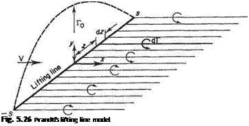
is the total circulation due to all the vortex filaments passing through the wing section at z. Physically the approximate theoretical model implicit in Eqn (5.32) and (5.33) corresponds to replacing the wing by a single bound vortex having variable strength Г, the so-called lifting line (Fig. 5.26). This model, together with Eqns (5.32) and (5.33), is the basis of Prandtl’s general wing theory which is described in Section 5.6. The more involved theories based on the full version of Eqn (5.31) are usually referred to as lifting surface theories.
Equation (5.32) can also be deduced directly from the simple, less general, theoretical model illustrated in Fig. 5.21. Consider now the influence of the trailing vortex filaments of strength <5T shed from the wing section at z in Fig. 5.21. At some other point z along the span, according to Eqn (5.11), an induced velocity equal to
will be felt in the downwards direction in the usual case of positive vortex strength. All elements of shed vorticdty along the span add their contribution to the induced velocity at z so that the total influence of the trailing system at z is given by Eqn (5.32).


