Representative Force and Moment Results
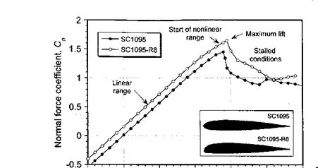
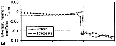
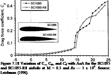
The data plotted in Fig. 7.18 show the low speed lift force coefficient, 1/4-chord pitching moment coefficient, and drag coefficient variations as functions of AoA for the
Angle of attack, a – deg.
 |
 |
 |
SC1095 and SC1095-R8 airfoils at M = 0.3.[26] The results are shown over an extended AoA that ranges from fully attached flow, where the lifting characteristics of an airfoil below stall are not substantially influenced by the presence of the boundary layer, to the fully stalled conditions where the flow has detached from the upper surface of the airfoil.
Below stall the resultant pressure forces on the airfoil are only slightly affected by the thickness and camber of the airfoil (provided they are small) and this is usually the case for most rotor airfoils. The lift on the airfoil section is proportional to its AoA and the local dynamic pressure. The lift per unit span of the blade can be written as
where Cia is the lift-curve-slope and is measured in per degree or per radian AoA. In coefficient form then
![]() Q = Cia {a — «о) in the low a range,
Q = Cia {a — «о) in the low a range,
where «о is the AoA for_zero lift or the zero-lift angle. The above relation comes under the category of linearized aerodynamics. For a real fluid, the lift varies linearly with AoA and is within about 10% of the above relation up to an angle of about 10-15°, depending on the Mach number and Reynolds number. Figure 7.18 shows that above a certain angle, the lift decreases and the pitching moment becomes increasingly negative (nose-down). This is a result of the onset of flow separation on the upper surface of the airfoil, which moves the center of pressure aft on the chord.
The effects of compressibility manifest as an increase in the effective AoA, which increases the lift on the airfoil. In other words, the effects of increasing Mach number appear as an increase in lift-curve-slope. In linearized subsonic flow, this increase in lift-curve – slope is given mathematically by the Prandtl-Glauert or Glauert rule [see Glauert (1927, 1947)1, where
where 2tt is the lift-curve-slope in incompressible flow and the Glauert factor is f = л/і — M^, with Mqo as the free-stream Mach number. The Glauert correction factor is found to give good agreement with experimental measurements of the lift-curve-slope of airfoils of thin to moderate thickness-to-chord ratio, and will be a sufficiently accurate correction to apply in practice. An example is shown in Fig. 7.19 where the lift-curve-slope for several airfoils in the NACA 00-series is plotted versus Mach number. The agreement with the Glauert factor is generally good for thinner airfoils (in accordance with its derivation) and/or up until the critical Mach number, M*. Beyond this, the developments of shock waves and their interactions with the boundary layer produce a reduction in the lift-curve- slope throughout the transonic range.
Kaplan (1946) suggests an improvement to the Glauert correction using the rule
![]()
![]()
![]() 2n
2n
CiSMoo) = —— +
p
where the second term represents the effects of thickness-to-chord ratio t/c. The Kaplan rule, however, tends to overpredict the magnitude of C/a(Moo) when compared to measurements and suggests a small further increase in Qa with increases in airfoil thickness. In practice the theoretical value of the lift-curve-slope can replaced by 2пгц (where r]i can be viewed as an efficiency factor) to account for such effects.


