ROLL CONTROL OF AIRPLANES
Roll control of aircraft has been and continues to be a major design problem as it is necessary to maintain or change the attitude of the aircraft throughout the operating speed range. The control of the airplane in roll is especially important during approach and landing to provide the pilot with the ability to counter and tor hold lateral displacements in the event of gusts and engine failure. Effective lateral control during landing is also needed for proper alignment with, and touchdown on the runway. With the development of STOL aircraft the lateral control effectiveness as a function of stalling speed is an important factor in determining the landing distance, as its design directly influences the CLX of the wing. If the required CLX is not compatible with the lateral control system the only alternative is a direct reaction type of control, which can lead to considerable difficulties. The problem of providing a roll control system for STOL aircraft is compounded by the need to use full span flaps to provide peak values of CLX.
During flight maneuvers control in roll is needed in combination with yaw control and is especially important for fighter type aircraft. The need to develop high rates of roll for fighter airplanes has led to considerable research and development and consideration of many different types of systems.
DEFINITION. An aileron is a flap type device located at the wing trailing edge and capable of inducing a rolling moment through a differential deflection. The deflection angle of one aileron is defined by the angle 6 and the total angle deflection is 6^- = + 62 . Rolling
moments are also obtained by the use of spoilers of various types. The deflection of the spoiler reduces the wing lift and thus provides the necessary moment.
(1) United States Patent Office Patent No. 821,393 “Flying Machine” dated May 22, 1906.
1. CHARACTERISTICS IN ROLL.
A wing symmetrical about the longitudinal axis of an airplane, no control deflections, will maintain its attitude unless disturbed by a change in velocity or angle, for instance due to a gust. A stable type wing will tend to return to the original undisturbed position but a means of control must be provided to allow the pilot to make the necessary corrections. The original method provided by the Wright Brothers was “Wing warping” but they also referred to flaps and other means in their patent (1). Since the original invention of a means for lateral control there have been hundreds of different types of devices used and investigated for controlling the airplane in roll. Some of the more important devices developed are illustrated in figure 1. The objective of the devices used for roll control is to provide a moment, thus it is necessary to produce either an increase or a decrease of lift on opposite wing panels. The rolling moment developed is defined in coefficient form by the equation
Q =M^/qbS (1)
where “b” represents the moment arm and C| is the non-dimensional coefficient. Since the aileron changes the geometry of the wing to develop a moment it becomes like a propeller or twisted helicopter rotor. With the initial deflection of the aileron the largest moments and roll accelerations are produced. As the rate of roll is increased the moment and acceleration are reduced due to the rolling velocity until the rate stabilizes. This is known as roll damping and is measured by the damping in roll coefficient
Cip=6 C^/6 (pb/2V) (2)
where “p” is the roll rate and “V” is the free stream velocity. The rate of roll achieved by a given system depends on the aileron effectiveness, the wing initial operating lift coefficient, the planform and its flexibility.

 UNSHIELDED HORN BALANCE
|
|
|
BALANCED AILERON |
|
SEALED INTERNAL BALANCE DEPRESSED FABRIC FUDGED FABRIC |
|
ORIGINAL CONTOUR
BEVELED TRAILING EDGE |
SURFACE COVERING DISTORTION
|
SPRING TAB |
|
RETRACTABLE ARC SPOILER
SLOT LIP AILERON PLUG AILERON SEE ALSO FIGURES 8, 21, and 22. Figure 1. Various types of lateral control devices. |
The aileron effectiveness ratio is measured by doc /d6 which as noted in Chapter ЇХ corresponds to the lift change due to the flap deflection compared t:> the lift change due to a change in section angle of attack. This measure is a function of the flap chord ratio and thickness ratio of the flapped section, figure 2, Chapter IX,
An aileron to be effective must of course operate on the wing section below the stall angle. Thus as a result of an aileron deflection lift will continue to increase. This is an important consideration, especially in the design of lateral control devices for vehicles which must land at low speeds such as STOL and general aviation aircraft.
The deflection of an aileron can result in high twisting moments in the wing structure which reduces the moment generated. As the speed is increased this adverse twist increases until the loads become high enough to cause a reversal where the airplane will roll in the opposite direction to the control deflection produced at low speed. This speed is known as the aileron “reversal speed ”.
(2) Lateral Control Specification:
(a) Perkins, Airplane Performance Stability & Control, J Wiley & Sons, Inc., 1949.
(b) Toll et all, Summary of Lateral-Control Research, NACA TR 868.
(c) Gillruth Control Requirements, NACA TR 755.
(d) Stability and Control Requirements, AAF Spec. No. R-1815.
(e) Creer, B. Y. and all Lateral Control Requirements, NASA Memo 1-29-59A.
Design Requirements. Many specifications have been published relating to the design requirements for roll control and the associated lateral control devices (2). The older specifications for lateral control generally related the requirement to the parameter pb/2V the helix angle described by the wing tip (see later section Helix Angle). For large cargo and bombardment type aircraft the minimum value of pb/2V was considered to be.07 for full aileron deflection and.09 for fighter types. The use of the parameter pb/2V is somewhat arbitrary for specifying lateral control devices and, therefore, better means have been developed. For instance, some specifications require the achievement of a certain bank angle after one second where other specifications require that the airplane be capable of making a 20° banked turn with or against a failed engine. It appears, however, that a better specification would include the effects of roll damping and aileron control power in terms of roll acceleration (2,e). Since lateral control specifications change periodically the current requirement must be established for design use.
In addition to providing the required roll effectiveness the lateral control system should also provide a linear roll response to a control motion without adverse coupling into yaw or pitch. Generally the yaw coupling is the most important and it is desired to develop the roll without retarding the forward movement of the up going wing. Spoilers have a favorable yaw characteristic in this sense.
Flap Type Ailerons. Conventional ailerons are basically “flaps”. However, their characteristics differ from those of elevators and rudders, as follows:
a) They are practically always part-span
b) The control forces are a combination between left and right
c) Their lift coefficient, on the average, are higher than that of tail surfaces
d) yawing (side-slipping) effects the characteristics of ailerons.
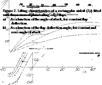
Figure 2 shows lifting characteristics of three sizes of plain flaps which could be used as ailerons as tested on an airfoil having an aspect ratio of 6. For example, as shown on figure 2,a, at a positive angle of deflection of 10°, the lift is shifted to higher levels, the level depending on the flap-chord ratio. Within the range of moderate flap deflection angles, the lift coefficient varies along straight lines, the slope being a function of the chord ratio corresponding to principles explained in connection with figure 2, Chapter IX. As in other control flaps, separation takes place (a) from the flap, above a limiting deflection between 15 and 20° ; (b) from the suction side of the airfoil and flap, as a function of the angle of attack (at lift coefficients roughly above 1.0). As with landing flaps, the maximum lift coefficient is increased corresponding to flap chord and angle of deflection. In separated condition,
the lift still increases (at a lesser rate) as a function of the angle of deflection, particularly as long as the flow is still attached to the forward part of the wing section. At a1 = constant = 0, the coefficient reaches a maximum in the vicinity of 6 = 70°, figure 2,b. As in tail surfaces, theoretical analysis is restricted to the linear portions of the lift forces (and the associated moments). The statistical results, for example as in figures 2, 7, 8 of
Chapter IX, readily apply to wing sections using plain aileron flaps.
|
|
Part-Span Flaps. Since ailerons practically never extend over all of the full wing span, the characteristics of part – span flaps are of interest. Experimental evidence is meager in this respect. Results of one investigation are illustrated, however, in figure 3, where the lift-curve slopes of the wing due to flap deflection is given as a function of the flap-span ratio for the cases
a) when increasing the flap span from the center line (case of a pair of wing landing flaps)
b) for a pair of outboard flaps, representing ailerons.
 |
 |
The lift produced increases with the span ratio as indicated on figure 3 and inboard flaps are more effective (as to lift, not as to rolling moment) than outboard flaps. Estimated slopes of the lift coefficient based upon the wing portions “covered” by the flaps, are also plotted in figure 3. The slope is highest in the wider vicinity of the wing center, and it drops off around the wing tips.
The lift-curve slope of the wing portions “covered” by ailerons, due to their angle of deflection, corresponds to the da /dcf ratio as in figure 2, Chapter IX. The dCL /doc to be used, is not that of the wing, however, (a) because the ailerons occupy only part of the wing span,
(b) because the deflection of conventional ailerons is antisymmetric (up on one side, and down at the other). Theory predicts that for the lift differentials plus and minus ACl of a pair of full-span ailerons, the effective aspect ratio is half of that of the wing.. If, for example, A = 6 the flap angle required to produce a certain lift differential must be based upon the induced angle of attack
da; /dCL = l/(rr 0.5 A) =
“ 57.3/(тґ3) ~ 6° (3)
where 57.3 = 180/гґ. Each wing panel’s effective :.ft angle (Chapter III) is then
da/dCL —10 + 6= 16°,
instead of 10 + 3 = 13°
and the effective lift-curve slope for ACL is 1/16° = 0.062 instead of 0.077 as for the wing as a whole. Conventional ailerons are only part-span, however. Considering, for example, an aileron flap adjoining the lateral edge of a rectangular wing, with the extremely small span ratio a/b = 0.1 only, we may expect the effective aspect ratio (as far as lift due to aileron deflection is concerned) to be between 1.0 (geometrical) and 2.0 (when assuming that the rest of the wing acts as an end- or reflection plate).
Assuming that equation (3) may still hold for aileron-span ratios in the vicinity of 0.5, the lift differential produced by a pair of antisymmetrically deflected ailerons of a given chord ratio is
Л CL » (dCL /doc (Sa /S)(doC /doc )rf (4)
where “2” indicates that the lift-curve slope corresponds to 1/2 the actual aspect ratio, or to 2 times the wing’s induced angle of attack. In the case of rectangular wings, the ratio of the effective area covered by one of the two ailerons, is:
SQ/S = a/b (5)
where “a” = spanwise length of one aileron flap. The moment arm “y” of the lift differentials (about the center line of wing or airplane) may be assumed to be that of the geometric center of Sa. The rolling-moment coefficient Cj = M^/qSb, of a pair of ailerons corresponding to a given area and chord ratio is then:
dC^ /d(A cf ) = A CL y/0.5 b (6)
where A cf = deflection-angle differential between one side and the other. In aileron systems where up and down deflections are equal, the differential is Д cf = 2/cfA
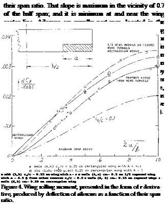
Part-Span Ailerons. Rolling moments due to aileron deflection are plotted in figure 4 against the span ratio. The slope of the lines in the graph is a measure for the rolling-moment effectiveness of ailerons as a function of

Rolling Moment Due to Aileron Deflection. When initiating or reversing a roll, motion is caused by a rolling moment. This moment can easily be measured statically using wind tunnel models of wings or airplanes. The angle of attack in the wing panels is uniform and cor stant in this case. The rolling moment “Mj” (5) is the consequence of lift differentials produced by antisymmetric aileron deflection. Theoretical methods are available (6) for predicting rolling moments due to aileron deflection. Considering a part-span aileron, the initial moment produced corresponds to:
a) the wing area “covered” by the aileron
b) the chord ratio of the aileron flap
c) the deflection angle of the aileron
d) the moment arm (aileron to center line)
e) the wing twist due to aileron loads.
(4) Ailerons and lateral airplane control:
(a) Toll, Summary, NACA T Rpt 868 (1947).
(b) Weick, Airplane Motions, NACA T Rpt 570 (1936).
(c) Weick, Lateral Control Research, NACA T Rpt 605 (1937).
(d) Weick, Ordinary Ailerons, NACA TN 449 (1933).
(e) Weick, Skewed Ailerons, NACA T Rpts 444 & 445 (1932).
(f) Weick, On Wing with Slat, NACA TN 451 (1933).
(g) Heald, Chord and Span of Ailerons, NACA T Rpt 343 (1930).
(h) Gilruth, Lateral Control Required, NACA T Rpt 715 (1941).
(i) Weick and Wenzinger, Ordinary Ailerons, NACA T Rpt 419 (1932).
(j) Johnson, Various Ailerons, NACA TN 2199 (1950).
(k) Naeseth, Influence of Aspect Ratio, NACA TN 2348 (1951).
(l) Fischel, At High Speed, NACA TN 1473 (1947).
(m) Fischel, Aspect Ratio, NATA T Rpt 1091 (1952).
(n) Higgins, Flap and Aileron, NACA T Rpt 260 (1927).
(o) Schneiter, Span and ТЕ Angle, NACA TN 1738 (1948).
(5) The indicates the longitudinal axis about which the
motion takes place.
(A)
 |
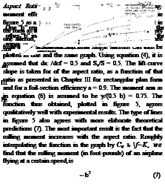 |
rectangular wings:
* NACA (4,m) with cf/c = 0.25 ■ NACA (6,k) with cf/c = 0.15
(B) tapered wings:
4 NACA (6, k) with с /с «0.20 x NACA (6,k) with c|/c **0.15 Q other sources with Cf/c – 0.20 and = 0.25
(C) wings with round tips
О NACA (6,k) with cf/c 0.20
Figure 5. The rolling-moment derivative of approximately halfspan ailerons as a function of wing aspect ratio.
(A) rectangular wings
(B) tapered wings
(C) wings with round tips.
Tunnel Testing. Conditions of antisymmetrical aileron deflection are not always simulated in wind-tunnel tests. This is particularly true when half-span models are used
(3) in closed test sections (8). Differentials as indicated in figure 5 are due to:
a) tapered as against rectangular wing shape cf/с = 0.20 as against = 0.25 and wind-tunnel interference
b) wings in open as against closed-type wind tunnels full — as against half-span wing models
c) “round” wing as against rectangular c. P/c ‘•= 0.15 as against = 0.25
In conclusion, rolling moments available for tapered wings under realistic conditions are less than those obtained when testing wind tunnel models with rectangular wings.
Aileron Effectiveness. The static rolling moment produced by aileron deflection may be approximated as being proportional to (/A(2a/b)vc77c). For aircraft where the hinge moment is a limiting factor Cw and thus :he hinge moment per degree of aileron deflection is a design condition. Evaluation of the data plotted in figures 4 and 5 leads to
dCb,/d(A& ) ^ k(/A(2a/b)/c^T"c) (8)
where after elimination of closed-tunnel and half-wing model results, the factor is
к ^ 0.0035 for “round” wings
^ 0.0040 for tapered wings
^ 0.0045 for rectangular wings
“Round” means shapes which are rounded off at the wing tips, thus cutting away from the outer end of the aileron flaps.
Rolling Velocity. The static rolling moment produced by aileron deflection, discussed so far, can only be present at the beginning of a roll. The moment is, therefore, a measure for the rotational acceleration of an airplane when going into a rolling motion as previously noted. Another measure for aileron effectiveness is the lerminal rolling velocity obtained in a steady roll. This rotational speed is usually given in the non-dimensional form of the speed ratio
u/V = pb/2V (9)
where the circumferential speed of the wing tips u = p(0.5b)
and p = angular velocity about the longitudinal airplane axis (in radians per second).
Helix Angle. Note that u/V is the angle against the normal plane of the helix line along which the wing tips move during the motion. Typical maximum helix angles of World War II fighter airplanes as listed in (4,a) are
u/V = pb/2V = between 0.06 and 0.12 (10)
measured in radians. The values obtainable at higher speeds (where stick forces are the limiting element, are only half of those stated. The rolling velocity of these airplanes are roughly between 50 and 130 degrees per second. As a function of their size it can be said that there is a tendency toward constant up or down wing-tip speed u. For example, at a lift coefficient of ~ 0.8 (after take-off or when approaching the landing field) a fighter with a span of 35 ft and an airliner with 120 ft, might both be able to move their wing tips, up or down, at a maximum speed in the order of 20 ft/sec.
Rolling Effectiveness. The effectiveness of a lateral control can be described by the ratio of the wing helix angle pb/2V to the aileron deflection angle. The helix angle described by the wing tip is uu, eq (9). Using constant units, radians or degrees we obtain the non-dimensional derivatives
dixj/db = l80d(u/V)/Tr6o (11)
In terms of the wing damping ratio eq (11) becomes
du>/d6 =dQ/Cipd6 (12)
Thus the effectiveness in roll is measured by the ratio of the rolling moment per degree to roll damping. This effectiveness parameter is a function of size of the aileron as well as the aspect ratio of the wing, and for practical purposes is
dw/d6~ (2a/b)cp /c//A~~ (13)
(7) Unconventional types of ailerons:
(a) Weick, Floating-Tip Ailerons, NACA T Rpt 424 (1932).
(b) Weick, Floating-Tip Ailerons, NACA TN 458 (1933).
(c) Weick, Short-Wide Ailerons, NACA T Rpt 494 (1934).
(d) Sawyer, On ТЕ of Wing flap, NACA T Rpt 883 (1947).
(e) Ashkenas, With Large-Span Flaps, NACA TN 1015 (1946).
(f) Dearborn, Zap Ailerons, NACA TN 596 (1937).
(g) Reed, External-Airfoil Flaps, NACA TN 604 (1937).
(h) Weick, External Ailerons, NACA T Rpt 510 (1935).
(i) Soule, Flight Tests Full-Span Flaps, NACA T Rpt 517.
(j) Platt, External Airfoil Flaps, NACA T Rpt 603 (1937).
(k) Fishel, Collection of Data, NACA TN 1404 (1948).
(8) The aileron angle should be corrected in the same direction as the angle of attack, with dof/d6 applied as factor of proportionality.
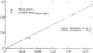
A wing with a large aileron and a small aspect ratio would therefore have a higher rolling effectiveness per degree deflection than the same aileron on a long wing. From the statistical values derived from test data, figure 6, we see that for example at (2a/b)cf/c/A equal to 0.1 that w/6 equals.5. Thus, the rolling velocity of an airplane can be calculated as a function of the aileron dimensions used and the aspect ratio. For the case of two ailerons deflected a total increment of 6 , the equation for rolling effectiveness is from figure 6 approximately
*/6 = 2.5(2a/b) /ср /с/ Уа~= u/V 6 (14)
so that the wing tip speed ratio is
u/V – ISO 8° (tu/6 )
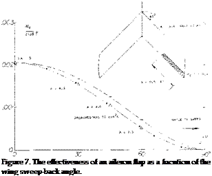
Sweepback. It is explained in Chapter IX how control flap characteristics change with the angle of sweep. As a consequence, aileron effectiveness reduces basically in proportion to cosM, when keeping the aspect ratio constant. Experimental results from a series of swept wings are plotted in figure 7, showing good agreement with the theoretical prediction even though the aspect ratio is not kept constant in this investigation.
Internal Force. In contrast to elevators or rudders, flap type ailerons are always provided in pairs. They moye antisymmetrically against each other and they are interconnected by means of a linkage system. In neutral position the hinge moments of the aileron flaps are usually somewhat “up”, on account of positive wing lift. The structural element (rod or possibly cable) connecting the two sides, therefore, takes up the corresponding “internal” force, for example in the form of tension.
![]()
 |
AILERON PARAMETER ( VcJ7c (I a/h)/VK)
Figure 6. Helix-angle derivative of airplane wings; statistical evaluation of wind-tunnel and flight tests as a function of a parameter indicating the aileron size. [95]
Stick Force. The control moment (stick force) is the sum of or the difference between (depending on the sign definition) the right and the left aileron. Primarily, therefore, the lateral stick force corresponds to the flap hinge moment derivative dCH /d6 . In fact, in a steady roll (with deflection, rate of roll and lift coefficient ~ constant) the hinge moments of plain ailerons can correctly be determined on the basis of figure 8, Chapter IX. On the other hand, stick forces for sudden aileron deflection (when initiating or reversing a roll) correspond to the total derivative as in equation (24) of Chapter IX, where CL represents the plus-minus ACL produced by the ailerons.
Differential Linkage. The wing’s lift and the flap hinge moment corresponding to that lift can be utilized to reduce lateral stick forces, when desirable. As mentioned above, each aileron flap usually has an up-floating tendency. By designing the linkage system connecting the two ailerons with the control stick (or wheel) in such a manner that the up-going flap has a somewhat larger deflection than of the corresponding down-going flap, it is realized that the mean deflection of the two flaps of 0.5(<f, +
cf2 ) is somewhat up. The lift or normal force supported on the surface of the pair of flaps operating at opposite angles, ailerons, helps reduce the hinge moments produced by their deflection. For practical results see (10).
|
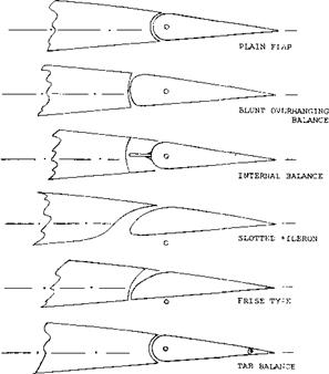
Figure 8. Various flap shapes and types of balance suitable to be used as ailerons. |
Nose Balance. To reduce the hinge moments of aileron flaps some type of overhanging nose can be used as described in Chapter IX and shown on figure 26. In fact, symmetrical (and comparatively blunt) open noses have occasionally been used. The external-horn balance was at one time found to be convenient and sufficient to balance the ailerons of smaller and low-speed aircraft, such as certain Fokker airplanes. Another possibility of balancing aileron flaps is the internal type, see figure 8. [96] [97]
|
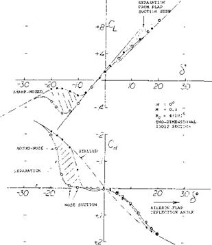
Figure 9. Slotted aileron flap tested (11 ,k) on rectangular airfoil with A = 2.4 in open wind tunnel. |
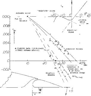
Slotted Ailerons. Because of the “always” positive lift of the wing to which ailerons are attached, flap-section shapes favoring suction-side flow are desirable. One such type is the slotted aileron, evidently fashioned after (or developed during the same period of time as) the slotted type of landing flap described in Chapter V. Figure 9 shows that such ailerons have unsymmetrical hinge- moment characteristics. The flap nose is comparatively inefficient at positive angles of deflection, while in the range of negative deflection suction forces of appreciable magnitude develop past the lower side of the nose as it emerges from the contour of the foil section. When combining hinge moments of one side up with the other side down, fairly straight control (stick) moments can be obtained, however, as illustrated later. Figure 10 presents hinge-moment derivatives for positive and negative deflection.
(11) Investigation of slotted and Frise-type aileron flaps:
(a) Weick, Slotted Ailerons, NACA T Rpt 422 (1932).
(b) Hartshorn, Frise-Type, ARC RM 1587 (1934).
(c) Kaul, Slot Shape, Yearbk D. Lufo 1941 p.1-315.
(d) Ehrhardt, Me-109 Ailerons, Messerschmitt WKB 2 (1943).
(e) Purser, Analysis of Data, NACA W Rpt L-665 (1944).
(f) Batson, Surface Curvature, ARC RM 2506 (1953).
(g) Aileron Flap Camber, ARC RM 2495 (1947).
(h) Letko, Frise-Type Aileron, NACA W Rpt L-325 (1943).
(i) Hoerner, Ju-228 Aileron Tested on Full-Scale Wing, Junker Rpt Kobu-Ew 895 (1941).
(j) Toll, Hinge Moment Parameters, NACA TN 1711 (1948).
(k) Junkers Wind-Tunnel Results Strote Graphs D-6761 (1941).
Yawing Moment When turning an airplane, both the ailerons and the rudder are deflected in proper direction. Most or all of the rudder displacement is required, however, not to make the turn, but simply to compensate for the adverse or “negative” yawing moment produced in the wing panels by deflection of conventional ailerons. Aileron flaps change lift; lift is increased in one* side and decreased in the other side of the wing. With the change in lift, induced drag (equal to local lift times induced angle) is increased in the outside wing panel, and it is decreased in the other panel. Considering a pair of symmetrically deflected ailerons, the induced-drag differential in each wing panel corresponds to
ACdl = ACl (o^O =
(ACl )2Clo /(1ҐA) (15)
where the function for (otL ) is in equation (3). Since ACl is positive on one side of the wing and negative in the other, a yawing moment is thus obtained corresponding to 2(ACdl )y, where у = moment arm to wing center line. The coefficient of the moment (11) of a pair of ailerons is then:
Cn = Mn/(q S b) =
4(У/Ь)(ДСи ) CLO / (VA) (16)
where Д CL is in equation (4). The ratio of yawing to rolling moment is
Cn/C* =-ACdL/ACl =
-4Clo /(‘TfA) = – 1.28 CLO /А (17) [98]
|
Figure 10. Statistical evaluation of the hinge moments of slotted aileron flaps. |
where the minus sign signifies that the yawing moment is adverse to the turning maneuver of the airplane. Such yawing moments coupled with roll control complicate handling of the airplane. “Negative” moments also reduce the magnitude of the rolling-moment and the resultant rate of roll, unless the pilot fully compensates by means of the rudder.
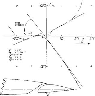
The “Frise” Aileron. This type aileron, figure 8, was invented (11) to reduce or to compensate for the unfavorable “negative” yawing moments associated with flap-type lateral control devices. It was expected that flow separation would soon take place after the sharp lower edge of the aileron nose moved out into the flow. Parasitic drag corresponding to such separation was to counteract the undesirable variation of the induced drag as described above. The disadvantages of this design are:
a) flow separation is bound to reduce effectiveness.
b) separation is likely to be accompanied by fluctuations and vibrations.
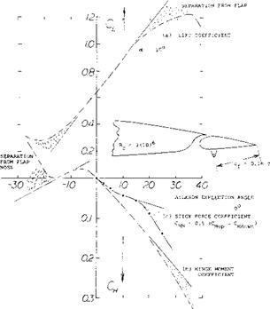
Figure 11 shows shape and characteristics of a typical Frise-type aileron flap. When deflecting this flap downward, lift increases steadily, and it continues to do so in the presence of flow separation developing along the suction side of the flap. This separation is evident from, and/or it results in a progressively increasing hinge moment. When deflecting the flap upward, strong suction forces develop at first around its lower leading edge as it emerges from the foil-section contour. Depending upon the sharpness of the edge, separation along the lower side’ of the flap starts at negative deflection angles between 7 and 15 . As a consequence, effectiveness reduces considerably while the hinge moment increases rapidly, from approximately zero to a level as indicated by a line connecting the two extremes of the hinge-moment function, figure 11.
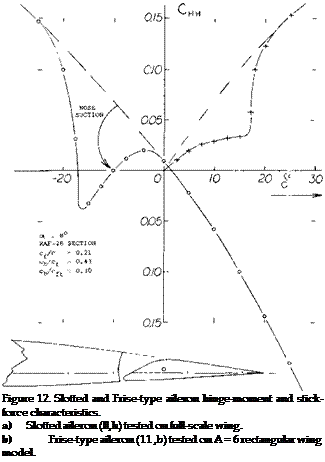
Stick-Force Coefficient. Average derivates as found, respectively, in the positive and negative branches of the hinge-moment function of slotted and/or Frise-type aileron flaps, are plotted in figure 10. When adding the values of the hinge-moment contribution from one side (down, for example) to that of the other side (up) we obtain a number representing the lateral stick force required to deflect a pair of ailerons. Dividing the combined value by 2, we obtain the stick force coefficient, properly referred to the sum of the aileron areas:
СЦу =: 0.5(CUup —Cydoujn) (18)
|
|
|
NOTE: OSCILLATIONS WERE OBSERVED AT THE NEGATIVE ANGLE OF STALL, WHERE CH INCREASES AND CL CHAISES SLOPE, Figure 11. Characteristics of a Frise-type aileron flap tested in a two-dimensional wind-tunnel set-up (11,h), for two different leading-edge radii. f Examples for the stick-force characteristics of two aileron flaps are presented in figure 12. Practical results are as follows: |
a) Comparatively irregular CM (cf ) functions of the single aileron can result in a surprisingly smooth stick-force variation. Truly, one side compensates for the other.
b) In case of the Frise-type aileron, the more or less sudden separation from the lower side of the flap nose produces a more or less steep increase of the stick – force coefficient.
c) A reduction of the hinge moments to half, to a third or possibly to a quarter seems to be feasible or to be the practical limit for this type of overhanging-nose balance.
d) Note that the effectiveness of the Frise-type aileron flap discontinues as separation from the nose takes place.
Stick-Force Slope. Considering the Frise-type aileron as in figure 11, it can be realized that when putting together the right-or-up with the left-or-down flap, the resultant stick force has a slope around the neutral position at 6 = 0, practically equal to zero. A control system with such a characterisitc is not desirable. To increase the stick-force slope, the flap deflection at which the slope of the hinge moment is zero, should be somewhat negative (such as in figure 9 and 12, for example). Means of shifting that angle are as follows:
a) Adjusting the neutral position of the two aileron flaps to a somewhat positive angle.
b) Displacing the flap nose sufficiently up so that it emerges from the foil-section contour at a somewhat more negative angle of deflection.
c) Combination of (a) with the use of a trailing-edge tab, compensating for the change of lift coefficient and pitching moment (Cmo) resulting from (a).
Taking into consideration that the hinge-moment and stick-force characteristics are also a function of angle of attack or lift coefficient, it will be appreciated that the type of overhang-balanced ailerons described above can be very cumbersome when attempting to reduce the hinge moment substantially.
Rigging-Up. The slotted type as well as the Frise form of ailerons are characterized by hinge moments:
a) increasing strongly within the range of positive flap deflection
b) roughly equal to zero (or somewhat unstable) for upward deflection.
As a consequence, the resultant control-stick moment essentially corresponds to the positive hinge-moment slope of down-going aileron flap. As mentioned above (under a), the relative contribution of the two sides can be changed, however, by changing the neutral position of the flaps. Pulling down both ailerons will thus increase the stick force required, while rigging up as described in (13,a, b) may appreciably reduce that force. Here again, the use of tabs (as mentioned in c above) may be desirable.
(13) Rigged-up aileron characteristics:
(a) Weick, Rigged-Up Ailerons, NACA T Rpt 423 (1932).
(b) Murray, Rigged-Up Ailerons, NACA W Rpt L-289 (1944).
 Tab Balancing. The various types of tabs described in Chapter IX can be and have been applied to ailerons. The linked or geared tab is particularly effective in reducing hinge moments and lateral stick forces to a fraction of what they are for plain aileron flaps. However, due to the reduction of the stick-free lift-curve slope in linked-tab configurations, possibly to zero for higher flap-chord – ratios, such arrangements may not be permissible in larger airplanes. Thus for the case of a rolling motion, the ends of the wing covered by aileron flaps may be deficient in damping qualities, caused by a reduced lift curve slope for the case of the stick or control wheel free. As a consequence, the airplane would continue to roll once this motion has started, and the airplane would not be stable about its longitudinal axis for the “stick-free” case.
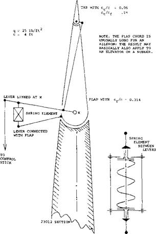
Spring-Tab Ailerons. Stability can be restored or maintained by restricting tab operation in such a manner that for zero hinge moment (corresponding to stick-free condition) and a suitable range of lower hinge moments, operation is just as that of an unbalanced plain pair of aileron flaps. This is done by means of the arrangement as in figure 13 where there are two levers “leading into” each aileron flap. One of these driving the tab is directly connected with the control stick, while the other one, rigidly attached to the flap, is linked to the main lever by means of a spring element. This element as shown in figure 13 has the following characteristics:
a) As long as the flap’s hinge moment is small, the element acts as a rigid link. This is obtained by pre – loading the spring. Control characteristics are then those of a plain flap.
b) When the flap hinge moment is large, the spring compresses corresponding to its mechanical constant. As a consequence, any lateral displacement of the control stick directly deflects the tab, which provides the moment necessary to drive the aileron flap in the opposite direction. This system thus behaves like a servo-tab type control.
c) Under conditions between the two extremes under (a) and (b) the torque deflecting the aileron flap is the sum of that due to tab deflection plus that corresponding to the force transmitted through the spring.
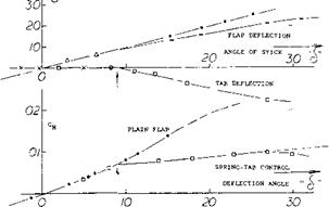
Effectiveness. The flap or control angle at which the spring starts to be compressed and the tab to be deflected depends upon the preload provided and the dynamic pressure at which the system is tested or used. In the case as in figure 13, the “critical” angle happens to be 6 = 9° . Above this angle, the tab deflects corresponding to d(dt. )/d“cf ” ~ -0.8, while the loss of flap deflection due to spring compression is d(A<f )/d“cf ’ “0.3. The
resultant loss of effectiveness is
Д (dCL /d6 ) =
(dCL /d6 ) ((d(A 6 )/d“6 ”) + (db /dSt }
(d6t /d“6 ”)) (19)
where (dCL /d5 ) = 0.033 as tested and (d& /d<St ) = (dot /d6t )/(dot /d5 ) = 0.2/0.6 = 1/3, as found in figure 2, Chapter IX. The numerical result is
(dCL/d& ) =
-0.033 (0.3 + (1/3) 0.8) = -0.019
As a consequence, the lift continues increasing above 6 = 9° at the rate of dCL /d6 = 0.033 -0.019 = 0.014. The reduction of effectiveness is appreciable in the case considered, where, Cp/c = 0.31.
Control Moment. The hinge moment of the plain aileron flap investigated, corresponds to CH<5 ^ 0.008. Disregarding the loss of flap deflection as stated above, the balancing moment provided by the tab can be expected to be as indicated in figure 36, Chapter IX where we tentatively find dCM Id6±° = —0.01. Consequently:
A(dCw /db ) = (dCM/d6t )(d6t /db )==
-0.01 (0.8) = -0.008
which is sufficiently close to the differential as tested between cT =10 and 20 . The average reduction at higher flap angles is roughly 50% under the conditions as tested. Upon reducing the spring’s preload, reduction of the control moment down to 25% could easily be obtained, while still retaining a range of no tab deflection in the order of plus and minus 5°.
Full-Span Wing Flaps. All modern airplanes are equipped with wing flaps in order to reduce landing and, to a lesser degree, take-off speed. Such flaps are, of course, most effective when extended over the entire span of the wing. Lateral (roll) control by means of ordinary ailerons, is then complicated by reasons as follows:
a) the ailerons interfere with the outboard part of the wing flaps, so that the rolling-moment coefficients obtained are somehow reduced.
b) the rolling moments in feet-pounds, being proportional to 1/CL, are appreciably reduced when increasing CL by means of wing flaps.
c) ![]()
![]()


![]()
![]()
![]()
![]()
![]()
![]()
![]()

 the adverse yawing moments connected with Пар-type ailerons grow with the lift coefficient, while those obtainable from rudder deflection (needed to balance the aileron-induced moments) reduce as 1/CL.
![]()
Figure 13. Example for spring-tab configuration on a 23012 airfoil section tested (14,b) between tunnel walls but with “aileron” flap only covering one half of the span.
The last complication can indeed come to the point where adverse yawing and side-slipping produce an adverse rolling moment large enough to move the airplane against the ailerons. To overcome the difficulties listed, improved and/or new types of lateral control devices have been developed. There are basically two types of such devices:
a) trailing-edge flaps similar to, or modifications of, ordinary ailerons
b) several types of spoiling devices at the upper wing side.
Trailing-Edge Deflection. An obvious method of roll control in flapped wings is by means of certain outboard portions of the wing (lift) flaps themselves. Figure 2 demonstrates, however, that not much effectiveness may be expected beyond a flap deflection in the order of 20°. The only means of improving the effectiveness is, in this case, differentiation of the aileron motion in such a manner that the upward displacement is larger than downward. In the end all that this control system amounts to is a pair of ordinary or possibly slotted ailerons, pulled down somewhat (say by 20°) together with some type of inboard wing flaps. All of the disadvantages listed above apply to the system.
|
|
|
Figure 14. Combination of a plain trailing-edge aileron flap with a slotted lift flap, tested (7,k) between tunnel walls. |
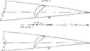
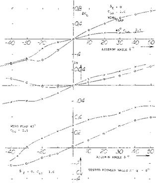
Duplex Flap. Figure 14 shows characteristics of a plain aileron flap attached to or located at the trailing edge of a slotted lift flap. Results of the two-dimensional investigation are:
a) The aileron effectiveness at 40° lift-flap deflection is but ~ 30% of that at zero deflection.
b) Effectiveness at negative aileron angles is generally slowly increasing, while that at positive angles is decreasing.
c) The wing-flap position has little influence on the variation of the hinge moments CH<? .
d) Because of (dCw/dod) the aileron is loaded in its neutral position.
On the basis of (b) aileron linkage could be arranged in such a manner that upward deflection is larger than downward. The “up-floating” hinge moment as under (d) would then reduce stick forces, but it would at the same time reduce the stability of the roll-control system. In conclusion, aileron effectiveness is not provided by duplex flaps where it is needed most, namely at higher lift coefficients (and at associated lower flying speeds).
Split-Flap Aileron. Split flaps are ordinarily not used for control purposes. Their lift-producing characteristics are similar to, if less effective than, those of conventional control flaps. Figure 15 shows the combination of two such flaps. Although both flaps could be deflected in the same direction as ailerons, only the upper one was used for control purposes during wind-tunnel tests. Results of the investigation are as follows:
a) Aileron effectiveness for a split-flap deflection of 60° is slightly higher than for neutral position.
b) Hinge moments for 60° lift-flap deflection correspond to the effectiveness as in (a).
c) Both effectivness and hinge moment have a tendency, near the neutral position of the aileron flap, of lagging. It appears that the flap has to penetrate “through” the boundary layer before it can become effective.
d) The “viscous” or parasitic component of drag increases as a function of the aileron deflection angle. This increase (connected with the upward, lift – reducing deflection of the flap) is very desirable in turning maneuvers of airplanes.
Regarding (d) it should be noted that the differential of the section drag coefficient is positive for negative (up) deflection of the aileron flap, while that in figure 14 is negative. In conclusion, it may be said that among the flap-type ailerons tested the split-flap type appears to be the most effective design to be used in combination with full-span wing flaps. In regard to high-speed drag (when the wing flaps are in neutral position) it seems to be necessary to deflect an outboard position of the lift flap together with the upper-side aileron flap for roll control.


