
Our heavyweight helicopter equal in the world does not have
In Rostov started production of the most load-lifting rotary-wing car The Russian holding «Helicopt[...]

Everything about aircrafts and helicopters. News and events in aviation worldwide. Civil, transportation, military helicopters and airplanes.

Everything about aircrafts and helicopters. News and events in aviation worldwide. Civil, transportation, military helicopters and airplanes.

Everything about aircrafts and helicopters. News and events in aviation worldwide. Civil, transportation, military helicopters and airplanes.

Everything about aircrafts and helicopters. News and events in aviation worldwide. Civil, transportation, military helicopters and airplanes.


Figure 2.18(c) shows the blade in air, with the distributed aerodynamic lift t(r, ty) acting normal to the resultant velocity; we are neglecting the drag forces in this case. If the shaft is now tilted to a new reference position, the blades will realign with the shaft, even with zero spring stiffness. Figures 2.18(d) and (e) illustrate what happens. When the shaft is tilted, say, in pitch by angle 0s, the blades experience an effective cyclic pitch change with maximum and minimum at the lateral positions (ty = 90° and 180°). The blades will then flap to restore the zero hub moment condition.
For small flap angles, the equation of flap motion can now be written in the approximate form
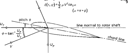 |
A simple expression for the aerodynamic loading can be formulated with reference to Fig. 2.19, with the assumptions of two-dimensional, steady aerofoil theory, i. e.,
where V is the resultant velocity of the airflow, p the air density and c the blade chord. The lift is assumed to be proportional to the incidence of the airflow to the chord line, a, up to stalling incidence, with lift curve slope a0. In Fig. 2.19 the incidence is shown to comprise two components, one from the applied blade pitch angle 9 and one from the induced inflow ф, given by
where Ut and Up are the in-plane and normal velocity components respectively (the bar signifies non-dimensionalization with aR). Using the simplification that Up ^ Ut, eqn 2.16 can be written as
where r = r/ R and the Lock number, y, is defined as (Ref. 2.12)
The Lock number is an important non-dimensional scaling coefficient, giving the ratio of aerodynamic to inertia forces acting on a rotor blade.
To develop the present analysis further, we consider the hovering rotor and a constant inflow velocity vi over the rotor disc, so that the velocities at station r along the blade are given by
where Oq is the collective pitch and 0s and 0c the longitudinal and lateral cyclic pitch respectively. The forcing function on the right-hand side of eqn 2.22 is therefore made up of constant and first harmonic terms. In the general flight case, with the pilot active on his controls, the rotor controls Oq, 0c and 0s and the fuselage rates p and q will vary continuously with time. As a first approximation we shall assume that these variations are slow compared with the rotor blade transient flapping. We can quantify this approximation by noting that the aerodynamic damping in eqn 2.22, Y/8, varies between about 0.7 and 1.3. In terms of the response to a step input, this corresponds to rise times (to 63% of steady-state flapping) between 60 and 112° azimuth (фб3% = 16 ln(2)/Y). Rotorspeeds vary from about 27 rad/s on the AS330 Puma to about 44 rad/s on the MBB Bo105, giving flap time constants between 0.02 and 0.07 s at the extremes. Provided that the time constants associated with the control activity and fuselage angular motion are an order of magnitude greater than this, the assumption of rotor quasi-steadiness during aircraft motions will be valid. We shall return to this assumption a little later on this Tour, but, for now, we assume that the rotor flapping has time to achieve a new steady-state, one-per-rev motion following each incremental change in control and fuselage angular velocity. We write the rotor flapping motion in the quasi-steady-state form
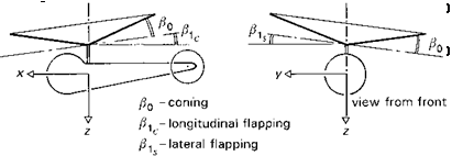
в = во + в1с cos ф + e1s sin ф (2.24)
во is the rotor coning and в1с and въ the longitudinal and lateral flapping respectively. The cyclic flapping can be interpreted as a tilt of the rotor disc in the longitudinal (forward) в1с and lateral (port) вls planes. The coning has an obvious physical interpretation (see Fig. 2.20).
 |
The quasi-steady coning and first harmonic flapping solution to eqn 2.22 can be obtained by substituting eqns 2.23 and 2.24 into eqn 2.22 and equating constant and first harmonic coefficients. Collecting terms, we can write
The partial derivatives in eqns 2.29-2.32 represent the changes in flapping with changes in cyclic pitch and shaft rotation and are shown plotted against Stiffness number for different values of y in Figs 2.21(a)-(c). Although Sp is shown plotted up to unity, a maximum realistic value for current hingeless rotors with heavy blades (small value of Y) is about 0.5, with more typical values between 0.05 and 0.3. The control derivatives illustrated in Fig. 2.21(a) show that the direct flapping response, 3^1c/991s, is approximately unity up to typical maximum values of stiffness, i. e., a hingeless rotor blade flaps by about the same amount as a teetering or articulated rotor. However, the variation of the coupled flap response, 3P1c/’391s, is much more significant, being as much as 30% of the primary response at an Sp of 0.3. When this level of flap cross-coupling is transmitted through the hub to the fuselage, an even larger ratio of pitch/roll response coupling can result due the relative magnitudes of the aircraft inertias.


