Additional Interpolation Schemes for FIE
For structural models with a single straight beam axis, the FIE method is a logical extension of beam theory. The projection algorithm assures that during deformation sections through the wetted surface that were perpendicular to the beam axis in the undeformed configuration preserve their shape. If however a structure consists of several angled beam segments, possibly part of different assemblies such as a wing and fuselage, a straightforward application of the described algorithm can lead to a non-smooth or non-contiguous deformed wetted surface.
With configurations comprising more than one assembly, any projection between surface components and structural model parts not physically connected must be avoided. This is exemplified in Fig. 3 for a high-lift device. The structural elements closest to surface points along the trailing edge actually belong to the flap. Projections based solely on shortest distance lead to a physically impossible transfer of loads and deformations over the flap gap. This is prevented by explicitly assigning structural elements to surface segments of the individual assemblies. In a preparatory step all collinear beam elements of each assembly are combined in element groups. Each assembly’s surface segment is given a unique identifier. In the ACM’s input data set, the element groups are then either assigned to surface segments or excluded from the projection algorithm. In the current example, the flap track elements should be excluded because they have no wetted surface segments as counterparts for mapping.
However, the strict application of this explicit assigning can make the wetted surface come apart at intersections between assemblies: Due to their projection on
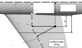
elements of different element groups, those neighbouring surface points which are part of different assemblies can experience incompatible deflections. The two surface segments necessarily contiguous in the undeformed configuration are no longer so after the deformation projection. The resulting defective mesh is not suitable any more for flow computations. This problem is resolved by means of an interpolation algorithm, which is exemplified by the wing-fuselage joint shown in the left image of Fig. 4. First, all seam curves between adjacent surface segments are detected. For a surface point belonging e. g. to the main wing, the projection is carried out onto the directly assigned element groups of the wing, giving a “direct” deflection uC^. Next, the projection is repeated for the element groups assigned to the neighbouring fuselage surface, which gives an “indirect” deflection u£pD. The weighted average of the two contributions is take
Alimit and dlimit are user-defined parameters which determine the extent of the interpolation region. The final surface point deflection is then interpolated from all considered projection results:
 ucfd = X Wtot, i ucfd, i with Wtot, i
i


![]()
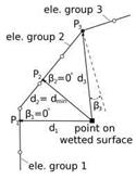
Fig. 4 left: Blending in the vicinity of intersections between surface segments of different assemblies, here at the wing-fuselage joint. right: Interpolation regions with non-unique mapping near kinks of the beam axis.
All interpolations have to be applied in the same manner also during the load projection as otherwise the conservativity would be violated (cf. Eq. (2)).


