CHARACTERISTICS OF WING DOWNWASH
In its conventional location, the horizontal tail of an airplane is obviously exposed to the downwash produced by the wing. Realistic prediction of downwash is somewhat complex, although the flow pattern can readily be understood.
Mechanism of Downwash. Considerable effort has been put into the analysis of downwash (11) as a function of:
a) wing plan-form shape and aspect ratio,
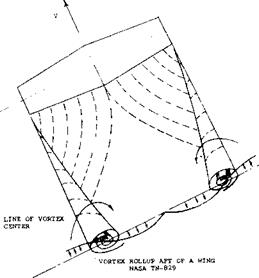
b) roll-up situation and longitudinal tail location, Figure 17. Horizontal plan, showing the geometry of vortex sheet
c) vertical location of the tail, in relation to the down – and hp-vortex Pair – wash sheet.
None of the solutions are complete, let alone simple enough to be used in practical design work and the agreement with experimental results is conditional. The mechanism of downwash can physically be explained, however. Consider the point (o) in figure 17, each of the lateral vortices emanating from the wing tips, induces a down – wash velocity at that point. The “bound” vortex (the lifting line) also induces a downwash component and this component directly representing the circulation around the wing sections, reduces as the point (o) considered is moved downstream.
(11) Analysis of wing downwash:
a) Flugge-Lotz, Report on Downwash w’out and with Slipstream, Ybk D Lufo 1938 p 1-172; also Lufo 1938 p 552 & 1940 p 161.
b) There are over 100 other references listed in (a).
c) Kaden, Rolling-Up Process, Ing Archiv 1931 p 141.
d) Silverstein, Downwash & Wake, NACA T Rpt 648 (1939).
e) Diederich, Calculation of Downwash, NACA TN 2353 (1951).
f) Spreiter, Trailing Vortex Sheet, J Aeron Sci 1951 p 21.
g) Helmbold, Downwash Analysis, ZFM 1925 p 291 & 1927
p 11.
h) Multhopp, Downwash Analysis, Lufo 1938 p 463.
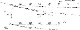
Trailing System. Figure 18 shows a lateral view (a) of the central part of the vortex sheet, originating from the trailing edge, and (b) of the pair of trailing vortices developing from the wing tips. The vortex sheet leaves the trailing edge in a direction corresponding to the aerodynamic angle of attack (measured against the zero lift line of the section). The maximum downwash angle is<fx = — oc0, accordingly. Behind a wing with elliptical distribution, the downward velocity of the tip-vortex cores is
w = – (CL I A) V4/tT3 ; or w /V = <XL 4/тг’2 ^ 0.4 odd
(21)
|
|
|
|
|
о MUTTRAY A = 5 ELLIPTICAL (13,d) X DITTO TIP VORTEX AT CL = 1 А МАСА 0.5 TAPERED A = 6 (13,d) |
|
VISCOUS WAKE AT сь = 1 |
|
МАСА RECT, ANGULAR WINGS,(13,3 1 |
|
MAXIMA IN VORTEX SHEET AND/OR VISCOUS WAKE |
|
THAT THE ’VERTICAL DIMENSION IS DRAWN TO THE SAME SCALE AS THE LONGITUDINAL |
where w and, both are negative quantities. The final velocity in the plane of symmetry is
w =-(CL/A)V(4/’rr); orw/V = (16/tf )o^l.6aT=£
The cores thus move down at 1/4 of the final downwash velocity in the plane of symmetry.
Downwash Due to Circulation. The component of down – wash representing the circulation around the bound vortex (lifting line) is not “permanent”. It affects the horizontal tail surface, nevertheless. For elliptical life distribution (along the wing span) the angle (in radians) due to circulation velocity “v” is basically
£,-= — v/V ~ — (0.25/Tf) C(_ (с/х) (22)
where x = downstream distance from the lifting line at the quarter chord point, in the center of the wing. In terms of the induced angle of attack <xi = — Cl/tTA,
£c/c^l = 0.25 (x/b) (23)
This function, plotted in the lower part of figure 19, reduces rapidly as the distance x – tail length) is increased. It is, therefore, desirable to locate the horizontal tail as far aft as possible in order to obtain good stability.
Rolling Up. Upon leaving the trailing edge of the wing, the vortex sheet immediately starts rolling up (11 ,c) at the lateral edges into a pair of tip vortices. Using terminology as in figure 17, the distance (12) behind the wing’s lifting line for roll up is for a wing with elliptical loading:
x/b = 0.28 А/С (24)
For example, at C ^ = 1 and for A = 5 (as in figure 18) the distance is x = 1.4 b. Thus, at the usual location of a horizontal tail, rolling up is not yet completed. After completion, the “sheet” has disappeared. In its place we have then a downwash “field” between the pair of trailing vortices.
Final Downwash. The magnitude of the downwash component resulting from the trailing vortices reduces as the roll-up process goes on. In particular, the angle ratio behind elliptical wings theoretically assumes the final value.
,£ /orL = (4/rrf= 1.62 ~ 1.6 (25)
Figure 18. Vortex sheet (in the plane of symmetry) and tip-vortex location as seen in the vertical plane. [104]
Along the center line of the wing, theory (11) indicates maximum values (found “in” the vortex sheet) in the form of a constant multiple of the induced angle of attack oc,; of the wing, approximately as follows :
|
plan form |
A |
£ /A t vortex sheet |
£ML rolled-up |
|
tapered to zero |
10 |
3.5 |
2.5 |
|
tapered ratio =1/3 |
7 |
2.2 |
1.8 |
|
elliptical |
any |
2.0 |
1.6 |
|
taper ratio ~0.7 |
6 |
1.7 |
1.4 |
|
rectangular |
6 |
1.4 |
1.3 |
|
rectangular |
10 |
1.3 |
1.2 |
In highly tapered (triangular) wings, lift and downwash are concentrated around the plane of symmetry. For wings with a rectangular plan form the downwash is relatively small in the plane of symmetry. Using equation (24) the downstream distance beyond which the “rolled – up” values tjocl are to be used is estimated using equation 24. No simple formulation for the transition from the “sheet” values to the final rolled-up levels are available however. Experiments confirm the influences of the lift coefficient, corresponding to the distance within which transition takes place. Results for a tapered wing (13,c) plotted in figure 19, are on the line roughly indicating an upper limit, for CL = 0.6 and coincide with a lower-limit line at CL = 1.5. Theoretically, this transition is a stabilizing component in the mechanism of longitudinal stability of airplanes. It can be estimated to increase the tail-moment contribution by a few %.
Variation in Vertical Plane. Figure 19 is meant to show maximum values of the downwash angle as they are found at the level of the vortex sheet coming from the trailing edge of the wing. The vertical position of that sheet (see figure 18) is approximately given by an angle measured from the wing’s quarter chord point and against its zero lift axis. The value of this angle is always larger than that of the final downwash angle. For a rectangular wing of aspect ratio 6, at a distance x/b = 0.5, the angle is, for example, ~ 2 o£ . It is an empirical observation, however, that maximum downwash angles are found in a “layer” located somewhat above the viscous wake sheet. Above and below the “maximum” sheet, the angle reduces in the manner as shown in figure 20. No simple theoretical formulation of the reduction is available. The experimental results in the graph may be approximated, however, by
d(A£/£x)/d|z/b| 1.5 (26)
where z = distance above or below the sheet. It can be stated that by placing the horizontal tail below the vortex sheet, longitudinal stability can be improved, particularly on account of the* downwash gradient along the path through which the tail of an airplane moves when changing the angle of attack.
|
|
|
|
|
|
|
|
|
|
|
|
|
|
Figure 19. Maximum downwash angle ratio “in” the vortex sheet, in the wing plane of symmetry, as a function of downstream distance x (13).
(14) Influence of fuselage upon downwash:
a) Liess-Riegels, Analysis, Ybk D Lufo 1942 p 1-366.
b) White, Fuselage Interference, NACA T Rpt 482 (1934).
c) Schlichting, Wing in Interrupted Flow, Ybk D Lufo 1940 p 81.
![]()
![]()

![]()

![]()
![]()


![]() □
□
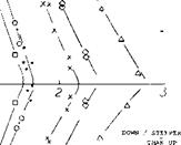
Figure 20. Downwash distribution in vertical plane of symmetry, behind plain wings as tested (13).
Fuselage Downwash Interference. All downwash considerations so far, apply to isolated wings. With the addition the fuselage in the form of a slender body the lift distribution changes across the span of the wing and thus a change of the average downwash at the tail is obtainable since
(a) As explained in context with figure 4, lift (and lift – curve slope) can be assumed to be increased at and near the wing roots with a corresponding increase of downwash (14,a).
(b) Viscous interference and/or flow separation along the wing roots may, on the other hand, reduce the down – wash.
(c) The fuselage leaves behind a viscous wake; downwash may be affected by this wake.
(d) As a consequence of cross or “2 oc ” flow, downwash can be expected to be reduced at the horizontal-tail roots.
The net result of fuselage interference thus depends upon shape and on quality of the wing-fuselage combination. For example, in figure 15, the tail effectiveness ratio (1 + dzjdoc) is reduced from 0.45 to (0.87/0.91)0.45 = 0.43, when adding fuselage plus tail in comparison to tail without fuselage. It can thus be concluded that the downwash ratio is increased from d^/doc = (1 — 0.45) = 0.55, to (1 – 0.43) = 0.57 or 4%, as a result of fuselage interference.
Since this is small a practical assumption might be that with conventional smooth wind-tunnel models the influence of the fuselage upon the variation of downwash (de/doc ) might be disregarded, at least within the range of low and moderately high lift coefficients. There are, on the other hand, many examples, showing a reduction of downwash on account of viscous fuselage interference as discussed in following paragraph.
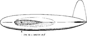
Wing Roots. Hardly any airplane design is as plain and smooth as, for example, the wind-tunnel model in figure 21. For instance, the real (if obsolete) airplane depicted in figure 22 (built before 1933) has a fuselage with rectangular cross-section. The lower edges of this shape lead into the leading edges of the wing roots. Ahead of each root, there is also an attachment supporting a pair of struts belonging to the landing gear. As a consequence, the flow along the wing roots is disturbed, if not separated at lift coefficients above 0.6. This disturbance causes:
(a) an increase, of the drag due to lift by ~ 30%, or 12% based on the total drag at CL = 0.7 (climbing).
(b) a reduction of horizontal tail effectiveness by 7% (viscous wake effect);
(c) a reduction of downwash (as shown qualitatively in the illustration) from an estimated ratio of dtjdoc = — 0.50 to-0.26.
While (b) is slightly destabilizing, the reduction of down – wash to ~ 1 /2, is stabilizing. Corresponding to A(dCm/dCL) = — 0.20 due to tail, the stabilized length is 20% of the chord, in the original rough condition of the airplane (with d£/d. oc = — 0.26).
|
WING: 0018/09 TAPERED A = 6, Rc = 3(10)6 VDT (23,d), c/1 = 1/4 FUSELAGE: l/d = !>.9, HINGED AT 1/4 OF THE LENGTH HORIZONTAL TAIL SURFACE: SH/S = 0.14; ^/c – 2.6,- VH = 0.36; Ajj = 4.5 |
|
LOCATION OF AERODYNAMIC CENTER AND NEUTRAL STABILITY POINT, % CHORD
Figure 21. Influence of wing-root fillets on stability characteristics of a simple airplane configuration (23,d). NP = neutral point. |
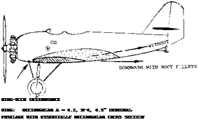 |
Wing-Root Fillets. To prevent separation at higher angles of attack, particularly along the upper (suction) side of low-wing airplanes wing root fillets are used. With suitable fillets, the maximum lift is increased, buffeting in wing and tail assembly is avoided and climb performance is improved. However, when first introducing wing-root fillets (possibly around or before 1930) it was soon discovered that they tend to increase downwash and thus to reduce longitudinal stability. In the airplane, as in figure 22, addition of large fillets extending downstream 1.7 c, and to 0.25 c above the trailing edge, and 0.3 c in spanwise direction (at the trailing edge), produced the following results:
(a) CLX (without power) increased from 1.2 to 1.3,
(b) downwash increased from dz/doc = — 0.26 to – 0.55,
(c) stabilized length reduced from (0.20 to 0.13)c.
Derivatives of a simple, clean and smooth airplane configuration are listed in figure 21. The stabilizing effect of the tail, in the configuration without fillets, is 15% of the chord, and that of the tail without downwash is 32%. It follows that without fillets, doc^/dot = (1 + d£/doc) = 0.15/0.32 = 0.47 and de/dot = – 0.53. When adding fillets, the aerodynamic center of the wing plus fuselage combination is shifted to the rear, approximately 1% of the chord. Against the new AC point, the stabilizing effect of the horizontal tail is reduced corresponding to 2% of the chord. The influence of the fillets corresponding to this 2%, leads to (1 + de/dar) = 0.41 and to dt/doC = — 0.59. The downwash increase with fillets is 12%. And while this increment is not comparable to that in the extremely disturbed airplane in figure 22, the influence of wing-root fillets upon stability should not be disregarded.
|
HORIZONTAL TAIL: |
SH/S = 0.19? |
H/c = 2-4: VH |
= 0.46; Aj |
|
WITHOUT POWER AND |
BELOW CL = 0. |
6 (NO SEPARATION): |
|
|
W‘ |
OUT FILLETS |
WITH FILLETS |
TAIL ALONE |
|
dCj/dof |
0.070 |
0.075 |
ESTIMATED |
|
(dC^drf )H |
-0.014 |
-0.010 |
|
|
(dCn/dCL)H |
-0.20 |
-0.13 |
-0.29 |
|
і – d(/a« |
0.74 |
0.45 |
|
|
d£/dcr |
-0.26 |
-0.55 |
|
Figure 22. Longitudinal stability characteristics of a full-scale airplane tested in a wind tunnel (14,b); in original form (no fillets) and with large wing-root fillets. |
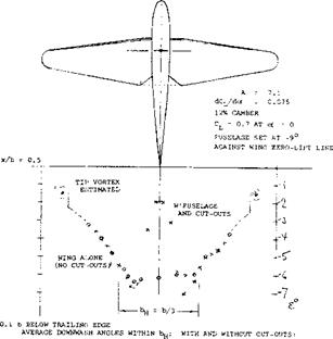
Cut-Outs. Downwash can be reduced by pulling the rear ends of the fillets up. While this produces a distortion of the vortex sheet, it does basically not mean that the derivative of the average downwash angle de/doc would be reduced. An efficient reduction of the derivative, can “only” be obtained by reducing the lift-curve slope in the center of the wing. This can, and has been done, by disturbing the flow past the wing roots on purpose, by means of roughness or obstacles such as spanwise strips of material placed near the leading edge. Another method is to reduce the wing chord by cutting away from the trailing edge at the roots. An example of such a cut-out is presented in figure 23. Downwash at the location of the tail is locally reduced from dt/dC^ — 7 to a minimum of — 2 . For an assumed span of the horizontal tail equal to 1/3 of that of the wing, the average downwash angle is reduced to di/dCL — — 5 , which is 70% of that of the wing without cut-outs (and without fuselage). On the basis of the lift angle of the configuration dcx/dCL~ 13 , the downwash reduction obtained, means an increase of the tail effectiveness corresponding to (1 + dt/doc) from 0.46 to 0.62. Since cut-outs might cause increased induced drag, stability is seen to interfere with performance particularly during climb.
|
df/dCL = -4.5° AND = -6.5° d*7dc* = -0.34 = -0.48 dc/dc* i = -1.6 = -2.3 |
NOTE: WITH A IUSELAGE AND WITH LARGE WING-ROOT FILLETS (NO CUT-OUTS)
DOWNWASH ANGLES ARE fH 10% LARGER THAN LISTED FOR WING ALONE (NO CUT-OUTS).
Figure 23. Example (13,c) for the influence of wing-root cut-outs upon the downwash at the location of the tail.


