Effect of Airfoil Shape on Hitching Moment
The effect of the airfoil shape on the pitching moment characteristics is of utmost concern for the design of helicopter rotors. As mentioned earlier, experiences with cambered airfoils on early autogiros resulted in significant blade twisting and high control loads. For
Table 7.4. Variation in Center of Pressure for Example Airfoil
![]() AoA (deg.) -2 0 2 4 6 8
AoA (deg.) -2 0 2 4 6 8
xCD 0.146 0.500 0.298 0.273 0.264 0.259
|
|
|
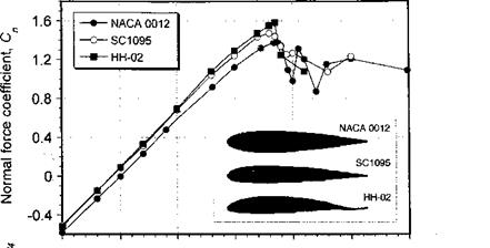
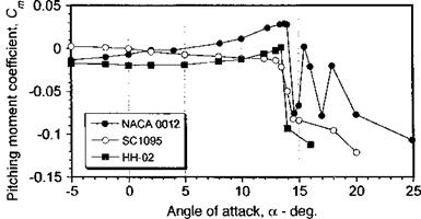
Figure 7.24 Comparison of lift and pitching moments on symmetric and cambered airfoils at Moo = 0.3. Data source: McCroskey et al. (1982). |
many years, this led to the exclusive use of conservative, low pitching moment (symmetrical) sections on nearly all helicopters. Today, blades are torsionally stiffer because they are made of composite materials and control systems can also be made stiffer without a weight penalty. This has allowed the better high lift capabilities of cambered airfoils to be utilized on modern helicopter blades.
Figure 7.24 shows lift and pitching moment results for a NACA 0012 in comparison with two cambered helicopter rotor airfoils, one with a relatively small amount of camber (the SC 1095) and one with a larger amount of camber (the HH-02). Both the NACA 0012 and SC 1095 airfoils have relatively low zero-lift pitching moments, Cmo, whereas the HH-02 has a higher pitching moment. The actual moments that can be tolerated on a given rotor blade depends on structural and other requirements, as well as the type of hub and control system. Traditionally, various individual airfoils have been developed based on the minimization of Cmo. But by allowing radially varying airfoil sections on the blade, pitching moment limits placed on the airfoil section itself can be relaxed somewhat; the main requirement is that the resultant moment that is reacted by the blade and control system be minimized as much as possible. As described in Chapter 6, this is sometimes accomplished by using a reflex cambered airfoil at the inboard sections of the blade where the need for a high maximum lift coefficient is not as stringent.
The effect of camber and chordwise position of maximum camber can be readily studied using the thin-airfoil theory (see Section 14.8 for the equations). The NACA four-digit airfoils have a camberline that can be conveniently expressed in terms of two parabolic arcs that are tangent at the position of maximum camber. The camberline is defined by
![]() m _ _2
m _ _2
Ус = —т(2px — x ) for x < p,
P
in
Ус = j.——– ~r[(l -2p) + 2px – x2] for x > p,
(1- Pr
where m is the maximum camber and p is the position of maximum camber, both as fractions of the chord. For example, the NACA 2412 airfoil has 2% camber at 40% chord with a thickness ratio of 12%. To use the thin-airfoil theory, the slope of the camberline is required. Differentiating the expressions for yc gives
 |
The thin-airfoil theory gives the pitching moment about the 1 /4-chord as C; —7t(A] — Af)/4, where
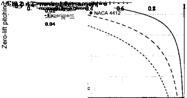
The results are summarized in Fig. 7.25 where the zero-lift pitching moment coefficient is plotted versus the point of maximum camber, p. Notice that forward camber has a much smaller effect on the pitching moment compared to camber applied near the trailing edge of the airfoil. Generally, the thin-airfoil theory will tend to slightly overpredict the pitching moment because of viscous effects, but the trends are correct.
 |
Chordwise position of maximum camber, p
Figure 7.25 Effect of chordwise position of maximum camber on pitching moment for the NACA 4-digit airfoils. Data source: Abbott & von Doenhoff (1949).


