Example Solutions for Mode Shapes and Frequencies
In this section, we consider several examples of the calculation of natural frequencies and mode shapes of vibrating beams in bending. One of the simplest cases is the pinned-pinned case, with which we begin. It is one of the few cases for beams in bending for which a numerical solution of the characteristic equation is not required. Next, we treat the important clamped-free case, followed by the case of a hinged-free beam with a rotational restraint about the hinge. Finally, we consider the free-free case, illustrating the concept of the rigid-body mode.
Example Solution for Pinned-Pinned Beam. Consider the pinned-pinned beam as shown in Fig. 3.35. The horizontal rollers at the right end are placed there to indicate that the resultant axial force in the beam is zero. Otherwise, the problem becomes highly nonlinear because it then becomes necessary to take the axial force into account, thereby significantly complicating the problem! The boundary conditions reduce to conditions on X given by
|
Substituting the first two boundary conditions into the general solution as found in Eq. (3.205), we find that
![]() A + A = 0
A + A = 0
a2(- A + D4) = 0
Recall that the constant a cannot be zero. To consider the a = 0 case we must take a solution in the form of a cubic polynomial, and the boundary conditions for this case do not yield a nontrivial solution of that form. Therefore, D2 = D4 = 0, and the solution for X becomes
X(x) = Di sin(ax) + A sinh(a x) (3.242)
 |
||
Using the last two of the boundary conditions, we obtain a set of homogeneous algebraic equations in D1 and D3
A nontrivial solution can exist only if the determinant of the coefficients is equal to zero;therefore
2sin(a£) sinh(a£) = 0 (3.244)
Because a = 0, we know that the only way this characteristic equation can be satisfied is for
![]() sin(a£) = 0
sin(a£) = 0
which has a denumerably infinite set of roots given by
Although this is the same set of eigenvalues that we found for the string problem, the relationship to the natural frequencies is quite different; viz.
EIaa (3.247)
![]()
|
As observed in the cases of the string and beam torsion, there is associated with the ith natural frequency a unique deformation shape called the mode shape (or eigenfunction). Each mode shape can be obtained from the spatially dependent portion of the solution by evaluating the function, X, (x), for any known value of a,. To find X, we substitute any value for a, back into either of the two scalar equations represented by the matrix equation in Eq. (3.243). It is important to recognize that the constants D1 and D now should be written as D1i and A,. Using the first of these equations along with the knowledge that sinh(a, l) = 0, we find that D3, = 0, leaving
Xi = Du sin (^ (i = 1, 2,…) (3.249)
where D1i can be any nonzero constant. For example, choosing D1i = 1, we find the mode shape to be
Фі = sin I (i = 1,2,…) (3.250)
which is the same mode shape as obtained previously for the vibrating string.
Example Solution for Clamped-Free Beam. Consider the clamped-free beam as shown in Fig. 3.36, the boundary conditions of which reduce to conditions on X given by
X(0) = X ‘(0) = X "(l) = X "'(l) = 0 (3.251)
As in the previous example, we can show that this problem does not exhibit a nontrivial solution for the case of a = 0. Thus, we use the form of the general solution in Eq. (3.206) for which a = 0. Along with the first two boundary conditions, this yields
![]() X(0) = 0 ^ E3 = 0 X'(0) = 0 ^ E1 = 0
X(0) = 0 ^ E3 = 0 X'(0) = 0 ^ E1 = 0
The remaining boundary conditions yield two homogeneous algebraic equations that may be reduced to the form
![]()
![]() sinh(al) + sin(al) cosh(al) + cos(al)
sinh(al) + sin(al) cosh(al) + cos(al)
cosh(al) + cos(al) sinh(al) – sin(al)
 |
It can be verified by applying Cramer’s method for their solution that a nontrivial solution exists only if the determinant of the coefficients is equal to zero. This is typical of all nontrivial solutions to homogeneous, linear, algebraic equations, and here yields
sinh2(al) — sin2(al) — [cosh(al) + cos(al)]2 = 0 (3.254)
or, noting the identities
 sin2(al) + cos2(al) = 1
cosh2(al) — sinh2(al) = 1
we obtain the characteristic equation as simply
cos(al) cosh(al) + 1 = 0
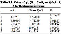
We cannot extract a closed-form exact solution for this transcendental equation. However, numerical solutions are obtained easily. Most numerical procedures require initial estimates of the solution to converge. Because cosh(al) becomes large as its argument becomes large, we can argue that at least the largest roots will be close to those of cos(al) = 0, or ail = (2i — 1)n/2. Indeed, the use of these values as initial estimates yields a set of numerical values that approach the initial estimates ever more closely as i increases. The values of ail (i. e., dimensionless quantities) are listed in Table 3.1. To six places, all values of atl for i > 5 are equal to (2i — 1)n/2. The corresponding natural frequencies are given by
To obtain the mode shapes, we substitute the values in Table 3.1 into either of Eqs. (3.253). The resulting equation for the ith mode has one arbitrary constant remaining (i. e., either E2i or E4i can be kept), which can be set equal to any number desired to conveniently normalize the resulting mode shape фі. For example, normalizing the solution by — E4i, which is equivalent to setting E4i = -1, we can show that
![]() фі = cosh(aix) — cos(aix) — в [sinh(aix) — sin(aix)]
фі = cosh(aix) — cos(aix) — в [sinh(aix) — sin(aix)]
E2i cosh(a, l) + cos(a, l)
![]()
 |
|
![]()
![]()
 |
|
E4i sinh(a, l) + sin(a, l)
The values of в also are tabulated in Table 3.1. For this particular normalization
фі (l) = 2(—1)’+1
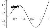
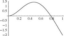
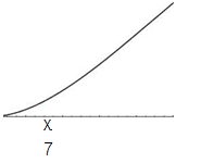
the first of which is left to the reader to show (see Prob. 10d). The first three mode shapes are depicted in Fig. 3.37. Note that as with previous results, the higher the mode number, the more nodes (i. e., crossings of the zero-displacement line).
Example Solution for Spring-Restrained, Hinged-Free Beam. This sample problem for which modes of vibration are determined is for a uniform beam that is hinged at the right-hand end and restrained there by a rotational spring with elastic
Figure 3.38. Schematic of spring-restrained, hinged-free beam
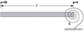 constant к = кEI/l. The left-hand end is free, as illustrated in Fig. 3.38. The boundary conditions for this case require that
X"(0) = 0 X //7(0) = 0 X(l) = 0
EIX"(l) = – kX'(l) or lX"(l) = – кX'(l)
The spatially dependent portion of the general solution is used in the form of Eq. (3.206). The two conditions of zero bending moment and shear at x = 0 require that
![]() X"(0) = 0 ^ E4 = 0 X’"(0) = 0 ^ E2 = 0
X"(0) = 0 ^ E4 = 0 X’"(0) = 0 ^ E2 = 0
The third boundary condition, that of zero displacement at x = l, can now be indicated by
X(l) = E1 [sin(al) + sinh(al)] + E3 [cos(al) + cosh(al)] = 0 (3.263)
The fourth boundary condition, a rotational elastic constraint at x = l, can be written as
l2 X"(l) + KlX'(l) = 0 (3.264)
so that
(al)2 {E1 [-sin(al) + sinh(al)] + E3 [-cos(al) + cosh(al)]}
+ Kal{ E1 [cos(al) + cosh(al)] + E3 [-sin(al) + sinh(al)]} = 0 This relationship can be rearranged as
|
{ |
al 1
cos(al) + cosh(al) +—– [-sin(al) + sinh(al)]
K (3.266)
al
+ E3 – sin(al) + sinh(al) + – [- cos(al) + cosh(al)] = 0
The simultaneous solution of Eqs. (3.263) and (3.266) for nonzero values of E1 and E3 requires that the determinant of the 2×2 array formed by their coefficients must
be zero. Setting the determinant formed from Eqs. (3.263) and (3.266) to zero, we find
{al
sin(al) – sinh(al) +—— [cos(al) – cosh(al)]
к
|
{ |
al cos(al) + cosh(al) +—- [- sin(al) + sinh(al)H = 0
(3.267)
After executing the indicated multiplications and applying the identities of Eqs. (3.255), the relationship becomes
![]() ^ [sin(al) cosh(al) – cos(al) sinh(al)] = 1 + cos(al) cosh(al) (3.268)
^ [sin(al) cosh(al) – cos(al) sinh(al)] = 1 + cos(al) cosh(al) (3.268)
This is the characteristic equation. As in the previous example, it is a transcendental equation that cannot be solved analytically. Note that for specified finite and nonzero values of к, we may calculate numerically a denumerably infinite set of the eigenvalues at l (for i = 1, 2,…) by a suitable iterative procedure. For such an iterative solution, we need initial estimates for the als. Note, however, that this equation is a special case in which we may solve for к as a function of al without iteration.
In the limit as к tends to infinity, we find eigenvalues in agreement with the clamped-free case, as expected. In the limit as к tends to zero, we can show that a rigid-body mode exists. The next example illustrates a procedure by which we may prove the existence of one or more rigid-body modes. It is important to note, however, that it is incorrect to try to infer the existence of a rigid-body mode because al = 0 satisfies Eq. (3.268) in the limit as к tends to zero; our general solution for X is valid only when a = 0.
For specified values of m, EI, l, and the stiffness parameter к, the eigenvalues can be used to determine the natural frequencies as
and the ith mode shape can be defined as
= sin(atx) + sinh(atx) + ві [cos(atx) + cosh(atx)]

![]() E3i /Eui can be obtained from the zero-displacement l, Eq. (3.263). When evaluated for the ith mode, Д
E3i /Eui can be obtained from the zero-displacement l, Eq. (3.263). When evaluated for the ith mode, Д
E3i = sin(q; l) + sinh(q; l) (3
Eui cos(ai l) + cosh(ai l) ‘ numerical values of which can be found once ai l is known for specific values of к.
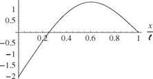
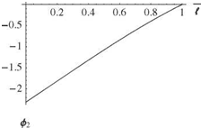
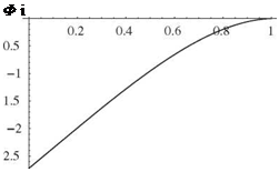
A sample set of numerical results for this example is shown in Figs. 3.39 through 3.41. The first three mode shapes are shown for к = 1 in Fig. 3.39. Fig. 3.40 shows the variation of ai l versus к for i = 1, 2, and 3, illustrating the fact that the frequencies of
Figure 3.39. Mode shapes for first three modes of a spring-restrained, hinged-free beam in bending; к = 1,
 |
|
«1 = (1.24792)^/~Ш/(тЄ4), on =
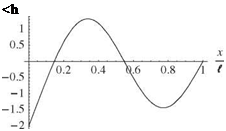 |
(4.03114)2^jEfJ(mt4), and o3 = (7.13413)^/El/(mS4)
the higher modes are much less sensitive to the spring constant than that of the first mode. Indeed, the first mode frequency (proportional to the square of the smallest plotted quantity in Fig. 3.40) tends to zero as к tends toward zero in the limit. This can be interpreted as the lowest-frequency mode transitioning to a rigid-body mode, which exists only when the spring constant is identically zero. In the limit as к becomes infinite, in contrast, the eigenvalues tend toward those of the clamped-free beam, as expected. Indeed, as Fig. 3.41 shows, when к = 50 the mode shape starts
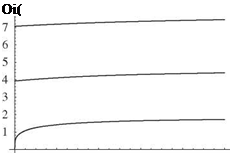 Figure 3.40. Variation of lowest eigenvalues at I versus dimensionless spring constant к
X
 (
(
Figure 3.41. Mode shape for fundamental mode of the spring-restrained, hinged – free beam in bending; к = 50, м1 =
(1.83929)2УElKmS4)
to look more like that of a clamped-free beam (with the fixity being on the right end in this example).
Example Solution for Free-Free Beam. The case of a uniform beam that is unconstrained at both ends, Fig. 3.42, may be considered as a crude first approximation to a freely flying vehicle. Their elastic and rigid dynamic properties are quite similar. In both instances, these properties can be described in terms of a modal representation.
The boundary conditions for this case require that
X "(0) = X "'(0) = X"(l) = X’"(l) = 0 (3.272)
The spatially dependent portion of the general solution to be used here again involves the sums and differences of the trigonometric and hyperbolic functions. Two of the E s can be eliminated by applying the boundary conditions at x = 0 so that
![]() X"(0) = 0 ^ E4 = 0 X’"(0) = 0 ^ E2 = 0
X"(0) = 0 ^ E4 = 0 X’"(0) = 0 ^ E2 = 0
The conditions at x = I of zero bending moment and zero shear X"(i) = 0, and X(£) = 0, respectively, yield the following relationships:
E1 [- sin(a£) + sinh(a£)] + E3 [- cos(a-f) + cosh(a-f)] = 0
(3.274)
E1 [- cos(a-f) + cosh(a-f)] + E3 [sin(a£) + sinh(a£)] = 0
Here again, the nontrivial solution to these equations requires that the determinant of the E1 and E3 coefficients be zero. This relationship becomes
sinh2(a£) – sin2(a£) – [cosh(a-f) – cos(a-f)]2 = 0 (3.275)
which simplifies to
![]() cos(a-f) cosh(a-f) = 1
cos(a-f) cosh(a-f) = 1
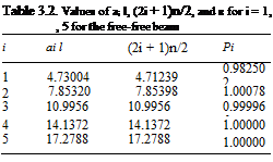 |
For large al, the roots tend to values that make cos(al) = 0. Unlike the clamped-free case, however, there is no root near n/2, and the first nonzero root occurs near 3n/2. Indeed, the ith root is near (2i + 1)n/2. Thus, the roots of this characteristic equation readily can be computed numerically to yield the eigenvalues ai l in Table 3.2. From these numerical values, the natural frequencies can be found as
![]() (3.277)
(3.277)
The mode shape associated with each eigenvalue can be defined as
= cos(aix) + cosh(aix) – в [sin(aix) + sinh(aix)]
The numerical value of the modal parameter в = – E1i / E3i, also tabulated in Table 3.2, can be obtained from either of the boundary conditions given in Eqs. (3.274). Using the first of those equations as an example, we obtain
![]() E1i cosh(ail) – cos(ail)
E1i cosh(ail) – cos(ail)
E3i sinh(ail) – sin(ail)
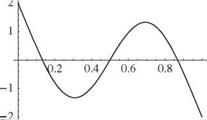
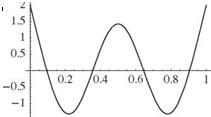
It can be shown that the first of Eqs. (3.274) would yield the same result by using the characteristic equation as an identity. The first three of these mode shapes are shown in Fig. 3.43.
In addition to these modal properties that can be used to describe the elastic behavior of the beam, there are also modal properties that describe the rigid behavior of the beam. These modes are associated with zero values of the separation constant a. Recall that a similar result was obtained for torsional deflections of a free-free beam. When a is zero, the governing ordinary differential equations for beam bending, Eqs. (3.197), become
![]() X"" = 0 Y = 0
X"" = 0 Y = 0
|
bx3 |
The general solutions to these equations can be written as
Y = ft + g
![]()
![]()
![]()
 |
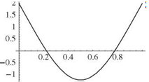 |
Figure 3.43. First three free-vibration elastic mode shapes of a free-free beam in bending
where the arbitrary constants, b through e, in the spatially dependent portion of the solution can be established from the boundary conditions. These conditions of zero bending moment and shear at the ends of the beam yield the following:
X "(0) = 0 ^ c = 0
X(0) = 0 ^ b = 0
(3.282)
X"(t) = 0 ^ b t + c = 0 X’"(l) = 0 ^ b = 0
It is apparent that all four boundary conditions can be satisfied with b = c = 0. Because no restrictions are placed on the constants d and e, they can be arbitrary. Thus, a general description of the solution in this case is
X = dx + e (3.283)
An important characteristic of this solution is that no relationship has been established between d and e. Therefore, they can be presumed to represent two independent motions of the beam. As written previously, e represents a rigid vertical translation of the beam because it is independent of x. The dx term, being linear
in x, represents a rigid rotation of the beam about the left end. It can be shown that when the rotational motion is taken to be about the mass centroid, it and the translation are orthogonal with respect to one another and with respect to the elastic modes. This suggests that the modal representation for these rigid-body degrees of freedom can be described by
0
![]() vrigid = У ‘ фі (x)fi(t)
vrigid = У ‘ фі (x)fi(t)
І =—1
where
ф-1 = 1 and ^—1(t) = translation
t (3.285)
ф0 = x – 2 and %0(t) = rotation angle
The time-dependent portion of the solution for these rigid-body motions is seen to be aperiodic. This means that natural frequencies for both rigid-body modes are zero. The two arbitrary constants contained in Y(t) can be evaluated from the initial rigid-body displacement and velocity associated with the translation and rotation. Thus, the complete solution for the free-free beam-bending problem can now be written in terms of all of its modes as
TO
v =J2 Фі (x)ii (t) (3.286)
І = —1
This example provides a convenient vehicle for further discussion of symmetry. It was already noted in the case of a vibrating string that systems exhibiting geometric symmetry have two distinct types of mode shapes—namely, those that are symmetric about the midpoint and those that are antisymmetric about the midpoint. As can be seen in the results, this is indeed true for the modes of the free-free beam. In particular, the rigid-body translation mode and the first and third elastic modes are clearly symmetric about the midpoint of the beam, whereas the rigid-body rotation mode and the second elastic mode are antisymmetric about the midpoint (see Fig. 3.43).
This observation suggests that the symmetric mode shapes could be obtained by calculating the mode shapes of a beam that is half the length of the original beam and that has the sliding condition at one end and is free at the other. Similarly, the antisymmetric modes could be obtained by calculating the mode shapes of a beam with half the length of the original beam and that has one end pinned and the other free. It also should be evident that a symmetric aircraft with high-aspect-ratio wings, modeled as beams and attached to a rigid-body fuselage, could be represented similarly in terms of the symmetric and antisymmetric modes of the combined body and wing system. That is, we may model the whole system by considering only one wing attached to a rigid body with half the mass and half the rotational inertia with appropriate boundary conditions.


