Our heavyweight helicopter equal in the world does not have
In Rostov started production of the most load-lifting rotary-wing car The Russian holding «Helicopt[...]

Everything about aircrafts and helicopters. News and events in aviation worldwide. Civil, transportation, military helicopters and airplanes.

Everything about aircrafts and helicopters. News and events in aviation worldwide. Civil, transportation, military helicopters and airplanes.

Everything about aircrafts and helicopters. News and events in aviation worldwide. Civil, transportation, military helicopters and airplanes.

Everything about aircrafts and helicopters. News and events in aviation worldwide. Civil, transportation, military helicopters and airplanes.


From the above discussion, we can see the importance of the two key parameters, kp and у, in determining the flapping behaviour and hence hub moment. The hub moments due to the out-of-plane rotor loads are proportional to the rotor stiffness, as given by eqns 2.14 and 2.15; these can be written in the form
Pitchmoment: M = — Nb—bp1c = —b®2^kp — 1^ вс (2.33)
Rollmoment: L = – Nb—в-в^ = —bq}Ip — 1^ f5s (2.34)
To this point in the analysis we have described rotor motions with fixed or prescribed shaft rotations to bring out the partial effects of control effectiveness and flap damping. We can now extend the analysis to shaft-free motion. To simplify the analysis we consider only the roll motion and assume that the centre of mass of the rotor and shaft lies at the hub centre. The motion of the shaft is described by the simple equation relating the rate of change of angular momentum to the applied moment:
Ixxp = L (2.35)
where Ixx is the roll moment of inertia of the helicopter. By combining eqn 2.27 with eqn 2.34, the equation describing the 1 DoF roll motion of the helicopter, with quasi-steady rotor, can be written in the first-order differential form of a rate response type:
![]() P — Lpp = L01c 01c
P — Lpp = L01c 01c
where the rolling moment ‘derivatives’ are given by
where the approximation that Sв << 1 has been made. Non-dimensionalizing by the roll moment of inertia Ixx transforms these into angular acceleration derivatives.
These are the most primitive forms of the roll damping and cyclic control derivatives for a helicopter, but they contain most of the first-order effects, as will be observed later in Chapters 4 and 5. The solution to eqn 2.36 is a simple exponential transient
|
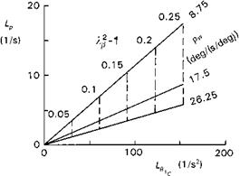
Fig. 2.22 Linear variation of rotor damping with control sensitivity in hover |
superimposed on the steady state solution. For a simple step input in lateral cyclic, this takes the form
p = -(l – eLPt)0lc (2.38)
LP
The time constant (time to reach 63% of steady state) of the motion, Tp, is given by —(1/Lp), the control sensitivity (initial acceleration) by L$1c and the rate sensitivity (steady-state rate response per degree of cyclic) by
Pss (deg/(s deg)) = —-^ = —^ (2.39)
L p 16
These are the three handling qualities parameters associated with the time response of eqn 2.36, and Fig. 2.22 illustrates the effects of the primary rotor parameters. The fixed parameters for this test case are Й = 35 rad/s, Nb = 4, Ip/Ixx = 0.25.
Four points are worth highlighting:
(1) contrary to ‘popular’ understanding, the steady-state roll rate response to a step lateral cyclic is independent of rotor flapping stiffness; teetering and hingeless rotors have effectively the same rate sensitivity;
(2) the rate sensitivity varies linearly with Lock number;
(3) both control sensitivity and damping increase linearly with rotor stiffness;
(4) the response time constant is inversely proportional to rotor stiffness.
These points are further brought out in the generalized sketches in Figs 2.23(a) and (b), illustrating the first-order time response in roll rate from a step lateral cyclic input. These time response characteristics were used to describe short-term handling qualities until the early 1980s when the revision to Mil Spec 8501A (Ref. 2.2) introduced the frequency domain as a more meaningful format, at least for non-classical short-term response. One of the reasons for this is that the approximation of quasi-steady flapping motion begins to break down when the separation between the frequency of rotor flap modes and fuselage attitude modes decreases. The full derivation of the equations of flap motion will be covered in Chapter 3, but to complete this analysis of rotor/fuselage
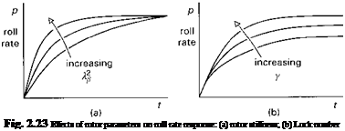 |
coupling in hover, we shall briefly examine the next, improved, level of approximation. Equations 2.40 and 2.41 describe the coupled motion when only first-order lateral flapping (the so-called flap regressive mode) and fuselage roll are considered. The other rotor modes – the coning and advancing flap mode – and coupling into pitch, are neglected at this stage.
|
л As 01c 01s +—————— = p + |
(2.40) |
|
T01s T01s |
|
|
О II i |
(2.41) |
where
and
 (2.43)
The time constants xp1s and Tp are associated with the disc and fuselage (shaft) response respectively. The modes of motion are now coupled roll/flap with eigenvalues given by the characteristic equation
к2 + — к + = 0 (2.44)
TPu TPu Tp
The roots of eqn 2.44 can be approximated by the ‘uncoupled’ values only for small values of stiffness and relatively high values of Lock number. Figure 2.24 shows the variation of the exact and uncoupled approximate roots with (к2в — 1) for the case when Y = 8. The approximation of quasi-steady rotor behaviour will be valid for small offset articulated rotors and soft bearingless designs, but for hingeless rotors with к^ much above 1.1, the fuselage response is fast enough to be influenced by the rotor transient response, and the resultant motion is a coupled roll/flap oscillation. Note again that the rotor disc time constant is independent of stiffness and is a function only of rotorspeed and Lock number (eqn 2.43).