Incompressible Flow about Wings of Finite Span
In 1908, Lanchester visited Gottingen (University), Germany and fully discussed his wing theory with Ludwig Prandtl and his student, Theodore von Karman. Prandtl spoke no English, Lanchester spoke no German, and in light of Lanchester’s unclear ways of explaining his ideas, there appeared to be little chance of understanding between the two parties. However, in 1914, Prandtl set forth a simple, clear, and correct theory for calculating the effect of tip vortices on the aerodynamic characteristics of finite wings. It is virtually impossible to assess how much Prandtl was influenced by Lanchester, but to Prandtl must go the credit. . .
John D. Anderson, Jr.
Introduction to Flight, 1978
6.1 Introduction
This chapter considers steady, inviscid, incompressible flow about a lifting wing of arbitrary section and planform. Because the flow around a wing is not identical at all stations between the two ends of the wing, the lifting finite wing constitutes a threedimensional flow problem. The two wing tips are located at distance ± b/2, where b is the wing span.
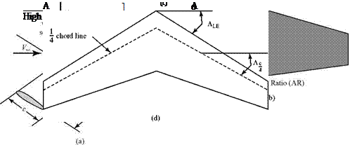
Certain terms must be defined before a study of finite wings can be begun (Fig. 6.1). The coordinate axis system used is shown in Fig. 6.1a. A wing section is defined as any cross section of a wing as viewed in any vertical plane parallel to the x-z plane. It also is called an airfoil section. The wing may be of constant section or variable section. If a wing is of constant section, wing sections at any spanwise station have the same shape (e. g., NACA 2312). If a wing is of variable section, the wing- section shape varies at different spanwise locations. For example, a wing of variable section might have a NACA 0012 at the root section (i. e., the section in the plane of symmetry at y = 0), then smoothly change in the spanwise direction until the wing had, a NACA 2312 section at the tip.
The planform area, S, of a wing is the projected area of the wing at zero angle of attack on a plane parallel to the x-y plane. If a wing has a tapered planform (Fig. 6.1b), the section chord lengths vary along the span. The taper ratio is defined as X = ct/cr. The airfoil sections for a straight-tapered wing of constant section all have
the same descriptor (e. g., NACA 0012), but they do not have identical sizes from root to tip. If the tip chord is smaller than the root chord (the usual case), then the tip section has the same thickness ratio as the root chord but not the same thickness dimension.
 |
|
The ratio of the square of the wing span divided by the wing-planform area appears so often in aerodynamic equations that this ratio has a name: the aspect ratio, AR = b2/S (Fig. 6.1c). For a rectangular planform, AR = b/c. The AR may be used to define a mean wing chord (or geometric average chord), c; namely,
c = b / AR. This mean chord should not be confused with the mean aerodynamic chord used in performance calculations. The mean aerodynamic chord is defined by:
1 b/2 2
mean aerodynamic chord = mac = — J 6/2[c(y)] dy
If the wing quarter-chord line is not parallel to the y-axis, then the wing is called a swept wing (Fig. 6.1d). The sweep angle to the quarter-chord line is used mostly in subsonic flow. Another sweep angle, the angle to the wing leading edge, is important for supersonic-flow considerations. If a swept leading edge and a straight trailing edge meet at a common point, the resulting planform is called a delta wing.
For convenience, a wing of rectangular planform is discussed initially; however, this chapter later addresses wings of arbitrary planform. Although the origin of coordinates may be taken at any chordwise station, it often is taken at the one-quarter chord point, as shown in Fig. 6.1a.
By definition, a finite wing has tips. If the wing is experiencing positive lift, then the average pressure on the lower surface of the wing is larger than on the upper surface. This pressure imbalance produces lift and also gives rise to a spanwise flow from the lower surface of the wing around the tips to the upper surface. Such a tip effect is not present when the wing is two-dimensional or of infinite span, with effectively no tips.
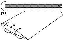
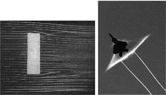
At the wing tip, there is a strong vortex set up that is due to the flow around the tip (Fig. 6.2a). Looking upstream, the sense of the tip vortex is clockwise at the left tip and counterclockwise at the right tip. These tip vortices trail downstream behind the wing and can be observed in wing-tunnel flow-visualization tests (Fig. 6.3a).
 |
 |
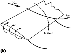
The spanwise flow field that is set up due to the flow around the wing tips means that the uniform flow that passes under the wing is given an outward velocity component so that the streamlines bend outboard (Fig. 6.2b). Similarly, the streamlines that pass above the wing surface experience an inward flow component and bend inboard. At the trailing edge, then, there is a mismatch in the spanwise velocity component. The spanwise flow just below the wing has an outboard component and the spanwise flow just above the wing has an inboard component. Such a velocity
discontinuity, occurring in essentially zero distance, was observed previously across a mean-camber line in two-dimensional thin-airfoil theory, where it was modeled by using a vortex. Likewise, the discontinuity in velocity that is present at the trailing edge of a finite wing is modeled by using vortices that begin at the wing trailing edge and trail downstream. The sense of the trailing vortices is clockwise for the left halfwing (looking upstream) and counterclockwise for the right half-wing. Each vortex filament trails downstream behind the wing like a thread. As might be expected, the magnitude of the spanwise-flow components and, hence, of the velocity discontinuity at the trailing edge and the related strength of the trailing-vortex filaments varies across the wing span. The spanwise-flow component, and the resulting velocity mismatch, is largest near the tip and zero at mid-span. Thus, the trailing vortices near the tip are much stronger than those farther inboard. It is shown later that the strength of the trailing-vortex system is closely related to the rate of change of circulation along the wing span.
 |
All of the trailing-vortex filaments together are called a vortex sheet. Such a sheet is observed in practice as a thin viscous layer of high vorticity coming off the wing trailing edge. In practice, this vortex sheet is unstable and, at a distance downstream of the wing, the entire sheet rolls up into two large contra-rotating vortices that continue downstream and ultimately diffuse under the action of viscosity. These large vortices can be observed in vapor trails left behind aircraft flying at an altitude such that the low pressure in the core (i. e., center) of the vortex causes the water vapor in the atmosphere to condense and become visible, thus acting as a visualization medium (Fig. 6.3b). Figure 6.3(b) also shows some effects of compressibility made visible by the same atmospheric conditions that show the tip vortices.
For purposes of analysis, the vortex sheet can be approximated, with small error, as being planar. It is possible to ignore the downstream deformation of the vortex sheet because the velocity disturbance at the wing caused by a segment of the trailing-vortex filament decreases by the inverse-square of the distance from the segment to the wing. Thus, a few chord lengths downstream of the wing, the distortion of the vortex sheet has negligible effect at the wing. Numerical solutions allow the vortex sheet to deform naturally, if desired.
The existence of a trailing-vortex sheet, which is not present in the case of an infinite wing, has major significance. It is shown later that a rectangular wing of constant section does not exhibit the same properties as the individual airfoil sections that comprise it. Regarding lift, for example, the lift-curve slope of a finite wing of constant section is found to be less than the (two-dimensional) lift-curve slope of the airfoil sections. Thus, it is important to be able to predict wing lift and to optimize lift for given constraints. The primary task in this chapter, then, is to examine the behavior of a finite wing and to discover how forces on the wing depend on wing-shape parameters.
Recall that for a two-dimensional airfoil, the drag was predicted to be zero according to the inviscid-flow model. That is, when the streamwise component of pressure force acting on an element of airfoil surface was integrated around the airfoil, the net drag force was zero. However, the drag of a finite wing is found to be nonzero, even in an inviscid flow. The presence of the trailing-vortex sheet affected the pressure distribution on the wing such that there now is a streamwise-force component, or an induced drag. This drag is the price for generating lift with a finite wing, and it must be added to the drag due to viscous effects to arrive at the total drag of a wing. The functional dependence of this induced drag on wing geometry must be investigated because all forms of drag must be minimized.
In addition to finding how wing lift and drag depend on the geometry of the wing, it is important to determine the distribution of force (primarily the lift force) across the span for a given wing geometry. Imagine a wing to be a beam cantilevered from the fuselage. If a beam structure is to be designed successfully, the force distribution along the beam must be known. Similarly, a structural analysis of a wing requires that the wing-spanwise-lift distribution, or spanwise loading,[22] be specified by an aerodynamicist.
This chapter begins with a discussion of the Biot-Savart Law, which provides a mathematical relationship to account for the presence of the trailing-vortex sheet at the wing. Because the flow around a finite wing must satisfy the Laplace’s Equation, it might be supposed that the finite-wing problem could be solved analytically by somehow distributing vortices over the wing surface, thereby paralleling the treatment of thin-airfoil theory in Chapter 5. This leads to a complex mathematical model. As a simplification, the vortices representing the wing are lumped together into a lifting line, which is a single finite-strength vortex filament extending spanwise from tip to tip and which represents the wing. The resulting theory is considered first in this chapter because it provides a fast and accurate way to uncover the variation of
wing properties across the span and thus the basic dependence of wing behavior on wing geometry. Following this discussion, two numerical solutions—termed vortex panel and vortex lattice methods—are discussed. Both methods model the finite wing by distributing vortices, either on the wing surface or on the mean-camber surface (i. e., thin wing), over the entire wing planform. Strip theory, a method to account for viscous effects if the wing angle of attack is small, is introduced next. To conclude this finite-wing chapter, several related topics are outlined—namely: ground effect, winglets, vortex lift, and strakes and canards.


