Our heavyweight helicopter equal in the world does not have
In Rostov started production of the most load-lifting rotary-wing car The Russian holding «Helicopt[...]

Everything about aircrafts and helicopters. News and events in aviation worldwide. Civil, transportation, military helicopters and airplanes.

Everything about aircrafts and helicopters. News and events in aviation worldwide. Civil, transportation, military helicopters and airplanes.

Everything about aircrafts and helicopters. News and events in aviation worldwide. Civil, transportation, military helicopters and airplanes.

Everything about aircrafts and helicopters. News and events in aviation worldwide. Civil, transportation, military helicopters and airplanes.


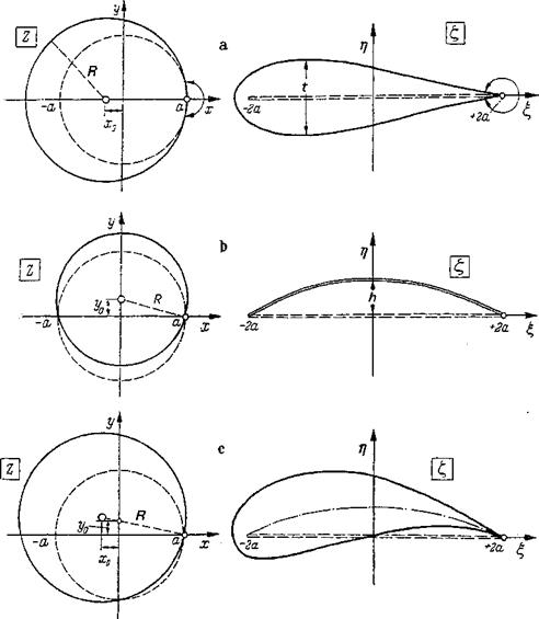
The Joukowsky transformation (mapping) function Eq. (2-21) is also particularly suitable for the generation of thick and cambered profiles. In Sec. 2-3-1 it was shown that this transformation function maps the circle z = a about the origin in the z plane into the straight line f = —2a to f = +2a of the £ plane (Fig. 2-8g).
The same transformation function also allows generation of body shapes resembling airfoils by choosing different circles in the z plane. These shapes may have rounded noses and sharp trailing edges (Fig. 2-14). They are called Joukowsky profiles, after which the transformation function is named. By choosing a circle in the 2 plane as in Fig. 2-14a, the center of which is shifted by x0 on the negative axis from that of the unit circle and which passes through the point z = a, a profile is produced that resembles a symmetric airfoil shape. It encircles the slit from —2a to +2a. This is a symmetric Joukowsky profile, the thickness t of which is determined by the location x0 of the center of the mapping circle. The profile tapers toward the trailing edge with an edge angle of zero.
Circular-arc profiles are obtained when the center of the mapping circle lies on the imaginary axis (Fig. 2-14h). When the center is set on +iy0 and the circumference passes through z — +a, the same mapping function produces a
|
Figure 2-14 Generation of Joukowsky profiles through conformal mapping with the Joukowsky mapping function, Eq. (2-21). (a) Symmetric Joukowsky profile, {b) Circular-arc profile, (c) Cambered Joukowsky profile. |
twice-passed circular arc in the £ plane. It lies between £=—2a and f = +2a. The height h of this circular arc depends on y0. Finally, by choosing a mapping circle the center of which is shifted both in the real and the imaginary directions (Fig.
2- 14c), a cambered Joukowsky profile is mapped, the thickness and camber of which are determined by the parameters x0 and yQ, respectively.
As a special case of the Joukowsky profiles, the very thin circular-arc profile (circular-arc mean camber) will be discussed.
Circular-arc profile In the circular-arc profile the mapping circle in the z plane is a circle, as in Fig. 2-14b, passing through the points z = Л-а and z = —a with its center at a distance y0 from the origin on the imaginary axis. The radius of the mapping circle is R = ayl + є? with ej = y0/a. The circle К is mapped into a twice-passed
profile in the £ plane, extending from f = —2a to £ = +2a. This profile has a chord length c = 4a and a camber height hja = 2ех, or
h 1
-7 = ^ (2-34)
It is easily shown that the profile in the f plane is a portion of a circle for any єі. For small camber (є? ^ 1), the profile contour is given by
![]() (2-35)
(2-35)
This profile is also called a parabola skeleton. For small angles of attack, a< 1, and small camber, the lift coefficient becomes
The lift slope dcildoi. is again equal to 2tt for small angles of attack, as in the case of the inclined flat plate according to Eq. (2-31). For the zero-lift angle of attack this equation yields a0 = —2(h/c). The pitching-moment coefficient about the profile leading edge becomes
см=-|(а + 41) (2-37)
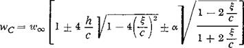
resulting in смо = —Tc(h/c) for the zero-moment coefficient whena0 = —2(hfc). The velocity distribution on the circular-arc profile is given for small camber and small angles of attack by
 (2-38)
The + sign applies to the upper profile surface, the — sign to the lower profile surface. The second term, which is dependent on the camber, represents an elliptic distribution over %. The third term, which depends on the angle of attack a, corresponds to the expression found for the inclined flat plate [Eq. (2-27)].
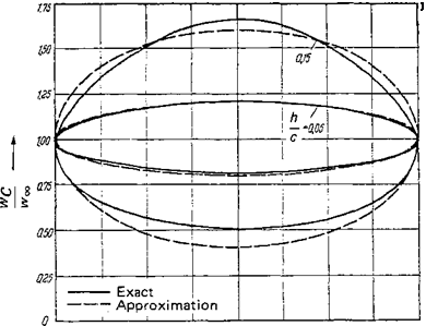
At the trailing edge, % = cj2, the velocity on the circular-arc profile is finite, whereas in general its value becomes infinitely large at the leading edge, = — c/2. Only for the angle of incidence a = 0 does the velocity remain finite at the leading edge. This is the angle of smooth leading-edge flow (no flow around the leading edge).* Velocity distributions, computed for this case, are shown in Fig. 2-15 for
Translator’s note: When the angle of attack of a thin profile (skeleton) is changed from positive to negative values, the stagnation point moves from the lower surface to the upper surface. Only at one angle of attack is the stagnation point exactly on the leading edge. This angle is called the angle of smooth leading-edge flow (S. L.E. F.). Obviously, here, no flow rounds the leading edge, which-in inviscid flow-would cause infinitely high velocities. Rather, the S. L.E. F. is a smooth flow past the leading edge. Only for a flat plate is the angle of S. L.E. F. equal to the angle of attack a = 0.
 |
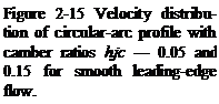 |
two circular-arc profiles of camber hjc — 0.05 and 0.15. For comparison, the exactly computed distributions are also given. The agreement is very good for small camber. For larger camber, some deviations can be seen.
Of particular interest is the largest velocity on the profile at a = 0. It occurs at the profile center | = 0 and is obtained from Eq. (2-38) as
WCmax = vv„^l+4^ (2-39a)
= (2-39&)
These equations allow a very simple estimation of the maximum velocity on a very thin circular-arc profile with smooth leading-edge flow.
Inclined symmetric Joukowsky profile The symmetric Joukowsky profile may serve as a further example. This profile is obtained from Fig. 2-14a when the mapping circle passes through the point z — 4-а and is placed with its center on the negative real axis at a distance x0 from the origin. The radius of the circle is
R = a + x0 = а(1 + e2) with є2 = ~ (240)
The unit circle and the mapping circle are tangent in z = a; that is, the tangents of the two circles intersect under the angle zero. Since the angles remain unchanged in conformal mapping, the trailing-edge angle of the Joukowsky profile is zero.[6] For a
very small thickness {z < 1), the profile chord length is c = 4a and the thickness
![]() ^=|V3e2 = 1.299E2
^=|V3e2 = 1.299E2
The maximum thickness occurs at </?= 120°, that is, at point c/4 from the leading edge. The profile contour is given by
![]() (242)
(242)
This profile shape is called the Joukowsky teardrop. The zero-lift direction of this profile coincides with the profile chord (the £ axis).
The lift coefficient is

cL = 27г(1 + e2) sin a
where the second expression is valid for small angles of attack. Accordingly, the lift slope dcLjdoc increases somewhat with profile thickness.
The pitching-moment coefficient about the profile leading edge becomes cm ~~(rr/2)(l +£2)0, indicating that the lift force center of attack (neutral point) lies at a distance c/4 from the profile nose. The velocity distribution on the contour of the symmetric Joukowsky profile is obtained in a way similar to that for the circular-arc profile. Presentation of the corresponding expression is omitted. In Fig.
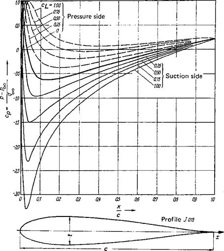
2- 16, pressure distributions on a symmetric Joukowsky profile of 15% thickness ratio are presented for various lift coefficients. At an angle of attack a = 0 (c^ — 0), the pressure minimum occurs at approximately 15% chord behind the nose. When the angle of attack increases, the minimum moves forward on the suction side and farther back on the pressure side.
Cambered Joukowsky profiles The Joukowsky profile with a mean camber line shaped like a circular arc is obtained by mapping an excentrically located circle with its center at z0 = x0 + iy0 (see Fig. 2-14c). Further generalizations of the Joukowsky mapping functions are given by von Karman and Trefftz [7], with profile thickness, camber height, and trailing-edge angle as the parameters. The mean camber line has the shape of a circular arc, however, as in the case of the Joukowsky profiles, resulting in a considerable shift of the aerodynamic center. For the elimination of this problem, Betz and Keune [7] developed suitable mapping functions.
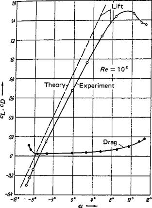
Experimental results Comprehensive three-component measurements on numerous Joukowsky profiles have been reported in [47]. Figure 2-17 shows a comparison of lift coefficients versus the angle of attack as obtained from theory and tests by Betz [31]. The agreement is quite good in the angle-of-attack range from a =—10° to
|
Figure 2-16 Pressure distribution of an inclined symmetric Joukowsky profile, t/c = 0.15, for various lift coefficients c^. |
a = +10°; the small differences are caused by viscous effects. The moment curves cm(cl) are i*1 agreement with theory up to large thickness ratios in the case of symmetric profiles; in the case of cambered profiles, however, the agreement is good only for small thickness ratios. The theoretical and experimental pressure distributions are also in good agreement, as can be seen from Fig, 2-18.
Concluding remarks The disadvantage of using the method of conformal mapping to determine aerodynamic properties of profiles lies in the necessity of first finding a mapping function. The resulting profile shape must then be compared with the desired shape. In general, it is not possible to know beforehand the proper mapping function that is mapping the desired profile shape on the circle. To a first approximation, this problem can be solved as shown by Theodorsen and Garrick [66]; see also Ringleb [32]. The methods for the treatment of profile theory by means of conformal mapping will not be discussed further, because the method of singularities, which will be discussed next, has proved to be more suitable and allows simpler computation of velocity distributions over a given profile. Furthermore, the method of singularities has the marked advantage over the method of
Figure 2-17 Lift and drag for plane flow around a cambered Joukowsky profile, after Betz [31]. Profile after Fig. 2-18.
 conformal mapping that it can be applied to three-dimensional problems (wings of finite span) whereas conformal mapping is strictly limited to two-dimensional problems. The great value of the method of conformal mapping remains nevertheless, because this method allows one to establish exact solutions for the velocity distribution on certain profiles that then can be compared with approximate solutions as obtained, for instance, by the method of singularities. For the design
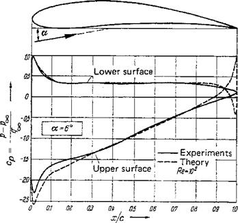 Figure 2-18 Comparison of theoretical and experimental pressure distributions of an inclined cambered Joukowsky profile resulting in the same lift, after Betz [31].
problem, that is, the problem of determining the profile shape for a given pressure distribution, Eppler [13] has developed a procedure that uses conformal mapping.