Propellers
![]()
![]()
 |
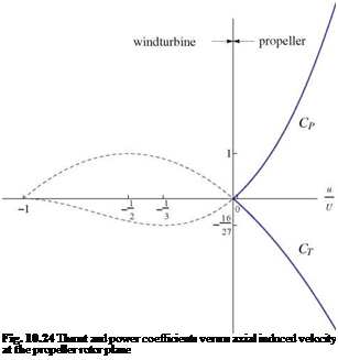
The actuator disk theory, applied to a propeller, yields the same results for the thrust and the power coefficients, except that the fluid accelerates behind the propeller so that the inductance is now positive, u2 = 2u > 0 and the thrust coefficient is negative, while the power coefficient is positive
 |
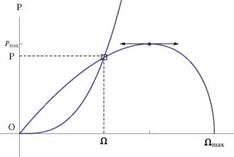
This is shown in Fig. 10.24. Note that the thrust and power vary monotonically with u, and do not have extremum values. The vortex model for the analysis of a propeller is identical to that of the wind turbine. The difference resides in the fact that the engine or motor power is given: typically, the engine characteristic is given, i. e. power versus rpm, and can be quite different for a gas engine and an electric motor. The characteristic curve for an electric motor is linear, whereas, for a gas engine it looks like the semi-cubic in Fig. 10.25. For a given geometry, at a given advance ratio, the power coefficient pT is sought by iteration, as with wind turbine analysis, until the values match at the rotor and the far wake. As a result, the power p and the
 |
 |
rotational speed Q are obtained, Fig. 10.25. The incoming flow velocity U and the induced axial velocity u, are then found.
The situation is slightly different for the design of a propeller, [20]. Given a rotor diameter, velocity and power (or torque) at a specified rpm, it is possible to design the rotor that will produce the maximum thrust (negative) in absolute value by minimization of the objective function
F (Г) = Ct (Г) + ХСт(Г) (10.106)
pT is known and there is no need to iterate the vortex structure which is determined once for all.
Goldstein [7], found an analytical solution to the optimum propeller that satisfies the Betz condition for lightly loaded rotors. He showed that the solution to the partial differential equation and boundary conditions, in the ultimate wake, can be mapped onto a two-dimensional problem, using the geometrical invariance of the flow along helices of same pitch as the vortex sheets. In dimensionless form the problem reads
 (10.108)
(10.109) where в is the polar angle measured from the y-axis, in cylindrical coordinates about the x-axis. ф is the perturbation potential, made dimensionless with Uu2/Q, where u2 is the induced axial velocity in the Trefftz plane. The solution in the (f, M)-plane can be expanded in terms of modified Bessel functions.
The finite difference solution on a Cartesian mesh system, Mj = (j — 1Mm, fi = (i — 1)Af, is readily obtained by relaxation with the five-point scheme for

(10.111)
– 3фі, 1 + 4фі,2 – фі, з = 0, фі, jx = 0, і = 2,…,іх – 1 (10.112)
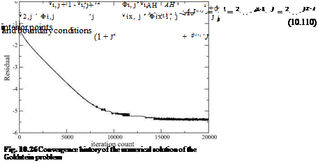
jb1 < j1 < jx, is the index that denotes the tip of the blade located at j = 1/adv. The convergence rate depends on the mesh aspect ratio Aj/AH. With a mesh of іх = 51 and jx = 201, extending to jmax = 2/adv, the convergence history for a relaxation factor rn = 0.5 is shown in Fig. 10.26. The circulation is obtained as the jump in ф across the sheet
rj = Ф1, j – фіx, j, 1 < j < j1 (10.113)
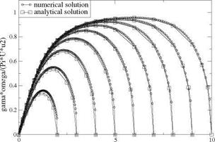
The normalized circulation ГQ/(n Uu2), for a two-bladed rotor and for a sequence of advance ratios, is compared with the analytic solution of Goldstein in Fig. 10.27.
|
r/adv Fig. 10.27 Circulation distribution—comparison with Goldstein analytic solution |


