PROPULSION LIFT AND STABILITY
![]()
 |
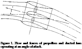
The lift force by the propulsion system may range from zero to over one hundred percent of the weight of the aircraft as in the case of helicopters. The propulsion system of STOL airplanes may generate lift directly or may induce increased levels of lift from the increased velocity of the slipstream passing over the wings and fuselage. The addition of lift with boundary layer control either by blowing or sucking is a form of propulsion lift, as power must be directly expended. In this context all types of lift could be thought of as powered lift; however, we shall define propulsion lift as that generated by the device normally used only for overcoming the drag of the airplane. The effects of the wash or slipstream on the wing lift produced by the propulsion devices will also be included in this chapter. The lift increment from boundary layer control through the use of power by internal blowing or sucking is discussed in Chapters V and IV.
Because the lift force produced by the propulsion device can be large it has an important effect on the stability of the airplane. This will be considered in terms of the lift, moments and interaction developed by the propulsion device.
THRUST DEVICE
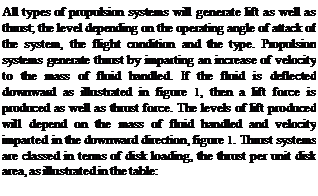
Helicopter Rotor VTOL Propeller STOL Propeller Conventional Propeller Ducted Fan Lift Engine Turbo Fan Jet Engine
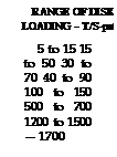
The thrust or the lift to power ratio of the engine types given in the above table operating at the static condition is given on figure 2. The large thrust to power ratio shown at low disk loadings is the reason for the use of these loadings on helicopter rotors. The propulsion devices given in the above table are also listed in the order of the mass flow handled. The largest devices handle the greatest mass flow and give the fluid the smallest increase in velocity since the mass flow,
m = P A A V
T – m д V
where V is the velocity through the disk area A and V is the increment of velocity imparted to the air.
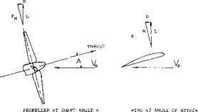
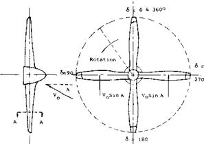
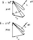
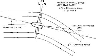
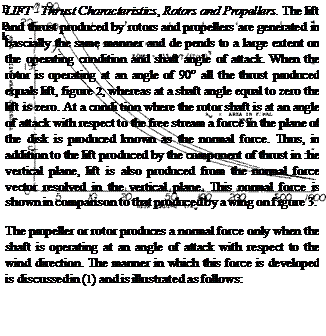
Consider a propeller operating at an angle of attack as shown in figure 4. Assume the propeller has four blades and that two of the blades are at the horizontal position. From figure 4 it will be noted that when the blades are at the horizontal position an increase in lift on the blade advancing down and a decrease in lift on the blade coming up are obtained. This is the result of the increase and decrease of section angle of attack and speed on the blades going down and up, respectively. It will be seen that these forces resolve themselves into a normal force in the axis of rotation and that the forces also result in a turning or yawing moment about the shaft.
 |
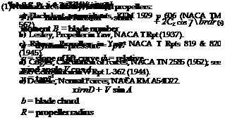 |
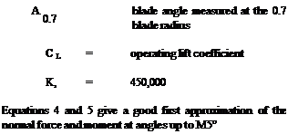
The equations for calculating the normal force and moment have been derived from blade element theory in a manner such as given in (1) as follows:
For a right-hand rotating propeller with positive lift normal force, the moment results in yaw couple to the left; the opposite being true for a left-hand propeller.
It can be shown for small values of A equations 2 and 3 can be reduced to
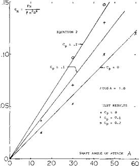
Comparisons of the test (2,c) and calculated values of normal force based on equations 3 and 4 show generally good agreement up to shaft angles of 45°, figure 5. At shaft angles above 60° the correlation is poor and more refined methods based on helicopter theories must be used.
![]()
|
||||||||||||||
|
||||||||||||||
|
||||||||||||||
 |
||||||||||||||
|
||||||||||||||
|
||||||||||||||
|
||||||||||||||
|
||||||||||||||


![]()
(3) Upwash ahead of straight wings:
a) Roberts, Twin-Engine Airplane, NACA TN 2192 (1950).
b) Yaggy, Survey (TN 2192) and Prediction (TN 25 28), NACA.
c) Rogallo, Analysis, NACA T Rpt 1295 (1956); also for swept wings in TN 2795, 2894, 2957 (1952/53).
(4) Normal Force V/STOL Aircraft:
a) Borst, The High-Speed VTOL X-100 and M200 Aircraft, Aerospace Engineering, August 1962.
b) Borst, The X-19 VTOL Aircraft, NYAS, Vol 107, 1963.
c) Kuchemann and Weber, Aerodynamics of Propulsion, McGraw-Hill Book Co., New York 1953.
|
Figure 5. Comparison of test and calculated normal force for an isolated propeller (2,c). |
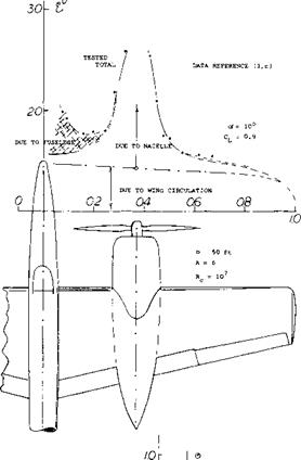
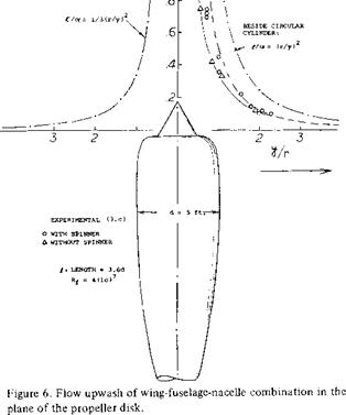
Induced Flow – Upwash. As shown in equations 3 and 4 as well as in figure 5, the flow angle into the disk of the propeller directly influences the normal force. Since propellers are usually installed in front of wing where an upwash is encountered, the inflow angle into the disk is changed from free stream thus influencing the normal force. These changes are large and may be estimated based on the test data of (3) where detailed measurements of the inflow velocity have been made. Computer programs based on theory are also available for estimating the inflow angle at the disk, taking into account the effects of the wing upwash and the variation of the flow about the wing and nacelle. From these methods the inflow angle A should be determined and used in equations 3 and 4 for calculating the propeller forces and moments.
(5) Ducted Fan Lift:
a) Mort, K., 7-Foot Diameter Duct Prop Test, NASA TN D-4142.
b) Goodson, Tilting-Shrouded-Propeller VTOL Model, NASA TN D-987.
c) V/STOLConf. 1966.
d) Grunwald, Shrouded-Propeller Configurations, NASA D-995.
e) Koenig, Wingless VTOL Aircraft, TN D-1335.
The wing upwash as illustrated on figure 6 generally results in a high inflow angle at the propeller at the climb condition when the aircraft is operating at low speeds and high coefficients. This increases the normal lift force of the propeller.
|
|
|
|
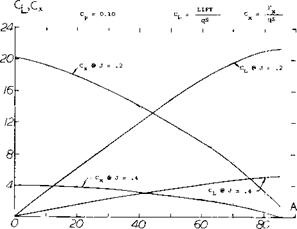
Propeller Lift and Thrust. The thrust and normal force measured normal to, and in the plane of the disk can be resolved into components in the direction of flight and in the lift direction as shown on figure 3. Resolved in this manner, the lift becomes a straight line function up to very high angles of attack, figure 7. The coefficients and Cx are based on the free stream dynamic pressure and the disk area S^>, thus
ClP = (TsinA + NcosA)q Sp (6)
Cxp = (TcosA – NsinA) q Sp. (7)
The lift and axial force coefficients CLp and CXp are a function of advance ratio as noted in figure 7 and depend on the detailed characteristics of the propeller as in dicated in equations 4 and 5. Note the straight line characteristic of the lift curve. Unlike a wing there is no sudden stall such as shown in Chapter IV. This characteristic is desirable for V/STOL aircraft that must operate through a large variation of angle of attack.
|
Figure 7. Total axial and vertical force variation of propellers operating at an angle of attack. |
Propeller and Rotor Moments. In addition to the thrust and normal force, a rotor or propeller operating at an angle of attack will produce yawing and pitching moments that become large, especially at high angles of attack. The yawing moment developed may be determined based on equations 3 or 5 or from wind tunnel test data, such as (2,c). The pitching moment becomes especially important at high shaft angle for V/STOL aircraft as it becomes a major factor in the design of the longitudinal control power.
For conventional airplanes the yawing moment produced by the propellers is destabilizing for tractor installations if all propellers are rotating in the same direction. This destabilizing moment is usually referred to as the fin effect (l, c) and is a function of the diameter and blade area as noted in equation 5. Since the yawing moment of a propeller at an angle of attack is dependent on the
direction of rotation it can be eliminated on a multipropeller aircraft with the use of opposite rotation.
Normal Force V/STOL Aircraft. A propeller is a good device for developing high lift power ratios at hover, figure 2, and can produce thrust as well as lift at forward velocity. For this reason it can be used on V/STOL aircraft performing a dual function of providing thrust and lift at all flight conditions. To do this it is necessary to use opposite rotating propellers operating in pairs so the large yawing moments associated with the development of large values of normal force can be cancelled.
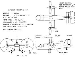
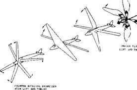
With such a system a linear lift force is obtained with angle of attack and it is possible to obtain lift forces of sufficient magnitutde to fly an airplane without wings (4). This principle was demonstrated with a full scale airplane, figure 8, where the propellers provided approximately 70% of the lift force at a forward speed of 175 MPH.
In nature, the dragon fly is another example of the use of propulsive lift to fly without fixed wings, figures 9 from
(4) illustrates this principle. Although nature does not provide for complete rotation of the wings the rapid oscillation of the wings does simulate the action of a dual rotation propeller, thus providing thrust and lift from the same unit.
|
Figure 8. The Curtiss V/STOL X-100 airplane for demonstrating propeller lift with normal force. |
As noted in equation 2, the propulsive lift of a rigid propeller is dependent on the shaft angle of attack, the propeller diameter, the total solidity, as well as the operating condition. If the blade angle is varied cyclically the lift force can be further increased. This must be done by increasing the blade angle of the down going blade while decreasing the blade angle of the up going blade. The same mechanism used for increasing the propulsion lift could be used for control at hover and low speeds, as in the case of a helicopter.
|
Figure 9. Lift and normal force in nature as shown by the flight of the dragon fly. |
The use of the propulsion system to generate lift requires that the shaft angle be low to obtain high values of L/D. From figure 2 it will be noted that
L/D = 1/tan A (8)
Thus, to obtain high values of lift drag the shaft angle, A, must be low. This requires that the q as shown in equation 4 be high so that the required lift is obtained at the low A angles.
Ducted Fan-Propellers. The ducted fan or propeller is effective for the production of lift as well as thrust when operating at an angle of attack above zero. The ducted fan has been therefore used and proposed for a number of V/STOL aircraft including a VTOL airplane without wings (5,e). Also because of its high thrust to power and lift ratio, the ducted fan has been applied for the power lift, control and thrust of airships. In the application of ducted fans for producing lift and thrust the duet can be operated at an angle of attack or the exit flow can be deflected with vanes to obtain lift.
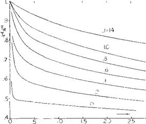
The ducted fan is an efficient device especially at low speeds as the interaction between the fan and the duct is mutually advantageous. The induction of flow through the duct by the fan produces a pressure reduction on the leading edge of the duct that gives a duct thrust force which adds to that thrust produced by the fan. The duct controls the flow at the fan and eliminates the radial flow and the tip losses that are associated with conventional open propellers. The elimination of the radial flow at the disk of the ducted fan is only accomplished if the duct is designed to produce the thrust level equal to that needed to obtain the ratio given on figure 9,a. This rotor thrust to the total thrust ratio, T^/Tp, is dependent on the power level of the rotor and the advance ratio, J. When the duct develops the required thrust ratio the duct flow controls the conditions at the disk and so prevents radial flow, assuming the rotor duct clearance is zero. When designing the duct to achieve the required thrust level a procedure must be used that accounts for the thrust produced
by the rotor and its advance ratio. This procedure is also used for determining the velocity at the rotor as induced by the duct so that the performance of the rotor can be calculated using a procedure such as is given in Chapter II.
The thrust developed by the ducted fan is dependent on the blade to duct tip clearance. These losses are large unless steps are taken to seal the tip or reduce the clearance to a minimum. The efficiency of the fan corrected for the tip loss can be calculated from the equation
/^ =(1.00002 – 2.654Rc/R-158.35 (Rc/R)2+ 163(Rc/R|)
(9)
where /$. = the corrected duct fan efficiency /? = efficiency with zero tip clearance
Rc = clearance between the rotor tip and duct wall
R = rotor radius
|
|
Figure 9a. Rotor thrust to total thrust ratio for ducted fan required to control radial flow.
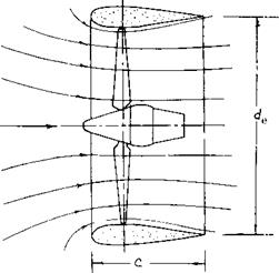
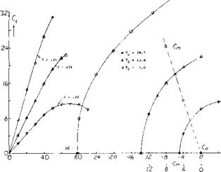
The ducted fan can be considered to be a ring wing with the fan inducing air through it, figure 10. As such the ducted propeller produces lift when operating at an angle of attack. The lift produced, (5,a) is a function of the advance ratio, the thrust coefficient and the angle of attack as shown on figure 10. The lift, drag, thrust and moment coefficients given on figure 10 are based on q and the projected area of the duct S. Thus
Tc = To ІЧ S ; CL = L/q s
CD = D/qS ; Cm = m/qS (9)
where S = cde, de is the exit diameter, and c the duct length.
The values of CL and Cp, Tc and moment coefficient C/n are high on figure 10 as the tests were conducted at low values of q and advance ratio. At the conditions tested the force in the drag direction is negative and so is a thrust force.
|
|
|
Figure 10. Lift variation of a large ducted propeller over a high angle of attack range. |
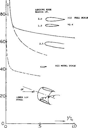
Lip Stall Ducted Fans. A ducted fan will tend to stall with an increase of the shaft angle of attack. Like a wing, stall takes place in the form of separation of the leadin g lip of the duct as illustrated in figure 11. The conditions where separation are encountered are a function of the shaft angle of attack, Reynolds number, inlet radius and the thrust coefficient Тз. Not only does the stall cause a loss of lift but it also causes a large increase in the noise level of the system and a decrease of thrust and efficiency. Because of the separation of the inner lip the propeller will encounter unsymmetrical flow which reduces the thrust and increases the blade stresses.
cx°
|
Figure 11. Inner lip duct lip stall as a function of angle of attack for ducted propellers. |
The angle of attack where separation can be expected on the upstream lip as a function of the thrust coefficient is illustrated on figure 11, based on tests of 4 and 7 foot diameter ducted fans and models. It should be noted that model tests of ducted fans indicate a much lower angle for stall even with large modifications of the lip radius (5,b). This illustrates the importance of q, Reynolds number and shows that model test results should be used with caution for predicting results especially where separation is involved.
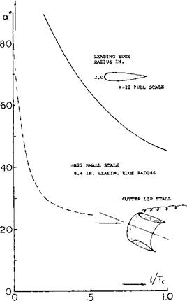
Tests (5,c) also have shown that separation will occur on the outside of the duct as illustrated in figure 12. This separation is also a function of the lip radius, Reynolds number and thrust coefficient. Upper lip separation is not as serious a problem as the separation on the leading lip, although an increase in drag is encountered. When separation takes place on the upper lip only a minor reduction in the slope of the lift curve is encountered.
Separation leading to duct stall can also be observed from plots of J/Tc a function of angle of attack as illustrated on figure 12 from (5,d). This curve shows that the separation considerably reduces the thrust produced by the duct.
|
Figure 12. Outer lip duct lip stall as a function angle of attack for ducted propellers. |
Duct Moments. Ducted propellers develop a pitching moment which increases with angle of attack as shown on figure 10. This pitching moment appears to be mainly a function of the lift coefficient and is mainly independent of the thrust coefficient and the advance ratio.
Unlike a propeller the yawing moment appears to be low for ducted fans with increases in angle of attack at least to an angle of 30 degrees, (5,a). It would appear that the length of duct in this case is sufficient to produce a symmetrical axial flow through the duct. Thus, it would be expected that the propeller or fan in the duct has very little effect on the overall lift as the normal force is essentially zero. When the flow separates on the forward lip this may no longer be the case.
Lift Engines. Light weight engines have been developed for direct lift applications. The lift produced by the engines is dependent on their placement on the aircraft. As shown in (5,c) the lift can be increased up to three times that of the static thrust of the engine depending on the configuration.
Engine Lift Turbofans, Turbojets. The lift produced by isolated turbofan or turbojet engines would be smaller per unit thrust developed than either propeller or ducted fans. This would be expected as the lift is developed based on the projected area of the engine nacelle, which would be smaller per unit power than the ducted propeller. The lift produced by turbofan engines is small in comparison to that of the complete airplane and is usually only important for interference and stability effects.
Because of the higher thrust coefficients of turbofan and turbojet engines the lip stall problem is delayed to higher angles of attack than shown for ducted fans. If operation is encountered at the higher angles the intake should be treated in much the same manner as the ducted fans discussed in the last section.


