Our heavyweight helicopter equal in the world does not have
In Rostov started production of the most load-lifting rotary-wing car The Russian holding «Helicopt[...]

Everything about aircrafts and helicopters. News and events in aviation worldwide. Civil, transportation, military helicopters and airplanes.

Everything about aircrafts and helicopters. News and events in aviation worldwide. Civil, transportation, military helicopters and airplanes.

Everything about aircrafts and helicopters. News and events in aviation worldwide. Civil, transportation, military helicopters and airplanes.

Everything about aircrafts and helicopters. News and events in aviation worldwide. Civil, transportation, military helicopters and airplanes.


The most significant contribution to the external forces and moments comes from aerodynamics. The three aerodynamic forces and moments in terms of nondimensional coefficients are
![]() Fxa — qSCx FyA — qSCy FzA — qSCz L — CiqSb M — CmqSc N — CnqSb
Fxa — qSCx FyA — qSCy FzA — qSCz L — CiqSb M — CmqSc N — CnqSb
Here, the coefficients CX, CY, CZ, Q, Cm, and Cn are the nondimensional body axis force and moment coefficients; S represents the reference wing area; qc is the mean aerodynamic chord; b is the wingspan; and qq is the dynamic pressure. Further theory of aerodynamic coefficients is discussed in Chapter 4. In particular, the coefficients would be dependent on Mach number, flow angles, altitude, control surface deflections, and propulsion system. For example, a deflection of a control surface would mean an effective change of the camber of a wing. This will affect the lift, drag, and moments and hence the aerodynamic coefficients. In fact, these are ‘‘static’’ coefficients and are generally determined experimentally from various wind tunnel tests. Hundreds of such experiments are required to be done for various scaled-down models of the given aircraft. The aerodynamic effects during aircraft maneuvering flights are captured in aerodynamic derivatives (Chapter 4). Lift and drag are explained in Appendix A. Here, these aerodynamic coefficients [7] are described briefly to connect the EOM with aerodynamics. Typical values of these coefficients are given in Figure 3.8a and b.
Lift coefficient: This coefficient, CL, is related to Cz. Its contributions come from wings, fuselage, and horizontal tail. It varies with alpha and Mach number (Figure A4). An increase in drag is always associated with an increase in lift. If the camber of the wings is not much, then the lift is obtained from the higher dynamic pressure. Generally, in an aircraft there would be some mechanisms to increase the effective camber of the wings. These are the additional small surfaces like flaps, the deployment of which would provide the required lift at low dynamic pressures. The dependence of the lift coefficient on the angle of sideslip and altitude is usually
 |
|||
|
|||
|
|
![]()
small and hence negligible. However, the effect of the thrust and the Mach number on the lift coefficient would be significant. With higher thrust, the peak of the lift curve (the lift coefficient plotted vs. alpha) could increase and the peak could also shift to a higher angle of attack. The effect of Mach number is such that the slope of the curve would increase up to a certain Mach number and then start decreasing. For supersonic speeds, the peak would decrease. The relationship between CL, CN, and CZ is given in Appendix A and Equation (3.29); CN is the normal force coefficient.
Drag coefficient: This coefficient, CD (Figure A5), is related to Cy, CN, and Cx in general. The latter is called the axial force coefficient. This is an important design parameter for the aircraft. In an ideal situation, one would always like to have minimal drag, no resistance to the aircraft, and the maximum possible lift (so that the aircraft can carry very large loads). This intuitive requirement defines the lift/drag (L/D) ratio and it is a performance parameter. The drag force is not necessarily a linear combination of several components: friction drag, form drag, induced drag, and wave drag. The individual contributions of these effects on the total drag would change with the flight conditions.
Side force coefficient: This force is the result of the aircraft having a sideslip angle different from zero. In general, the sideslip force depends on alpha, beta, Mach number, rudder control surface deflection, roll rate, and yaw rate.
Pitching moment coefficient: This is a very important parameter for the stability of the aircraft, especially in its derivative form, i. e., Cm. The latter is supposed to be negative in general. However, when it is positive, the aircraft does not have the required static stability. This aspect is discussed in Chapter 4. If the slope of the moment curve is high, then the aircraft is said to have pitch ‘‘stiffness.’’ Thus, a trade-off is required between static stability and maneuverability. The reduced/ relaxed static stability airframes are specially designed to obtain high L/D ratio and good maneuverability. The statically unstable configurations for obtaining such benefits, however, need to be artificially stabilized by feedback control filters/ algorithms. The moment coefficient primarily depends on alpha, Mach number, altitude, pitch rate, elevator (or elevon for delta wing aircraft) control surface deflection, inertial damping, aerodynamic damping term Cma, and flap displacement.
Rolling moment and yawing moment coefficients: These coefficients depend primarily on alpha, beta, Mach number, roll rate, yaw rate, aileron control surface (or elevon for the delta wing configuration) displacement, and rudder control surface deflection. These coefficients are better understood in the form of their components, which are discussed in Chapter 4.
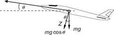
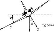
Next, to resolve the gravitational force acting on the aircraft into components along the body axis (Figure 3.9), the relative orientation of the gravity vector to the body axis system is required. If f, U, and C are the angular orientations of the gravity vector with respect to body x, y, and z axes, respectively, the components can be written as
FxG = – mg sin U
FyG = mg sin f cos U (3.17)
Fzg = mg cos f cos U
|
The third component comes from the engine thrust. Assuming the engine tilt angle to be sT with respect to the body X-axis and the total applied forces (accounting for the contribution from aerodynamic, gravity, and thrust) can be expressed as
Fx = qSCx — mg sin U + T cos sT
Fy = qSCy + mg sin f cos U (3.18)
Fz = qSCz + mg cos f cos U — T sin sT
At times, contribution from the gyroscopic moment from the propulsive system is added to the moment equations. This contribution is, however, neglected in the present model postulates. Although the forces and moments expressed here have been derived for the body axis frame of reference, the orientation of the aircraft has to be described with respect to a fixed reference frame. Assuming the body axis and the fixed frame to be parallel, three angular rotations in the following specific order are applied to determine the Euler angles (Figure 3.10):
• Rotate the fixed frame through yaw angle C to attain frame position x1,
y1, z1.
• Rotate x1, y1, z1 frame through pitch angle U to attain the position x2, y2, z2.
• Rotate x2, y2, z2 frame through roll angle f to attain the position x3, y3, z3.
The frame x3, y3, z3 is the final orientation of the body axis to the fixed axis. The relationship between the body axis angular rates p, q, and r and the Euler rates C, U, and f, derived from Figure 3.9, can be expressed as
f = p + q tan U sin f + r tan U cos f U = q cos f — r sin f (3.19)
C = r cos f sec U + q sin f sec U
Example 3.3
Express the inertial velocity components x, y, Z in terms of the velocity components u, v, w in body axis.
In Figure 3.10, rotation of the frame through ф to position xb y1, zi gives
x — u1 cos ф — v1 sin ф y — u1 sin ф + v1 cos ф Z — w1 (because rotation is about z-axis)
Next rotation through U to position x2, y2, z2 gives
u1 — u2 cos U + w2 sin U v1 — v2 (because rotation is about yj-axis) w1 — w2 cos U — u2 sin U
Final rotation through f to position x3, y3, z3 gives
u2 — u (because rotation is about yj – axis) v2 — v cos f — w sin f w2 — v sin f + w cos f
Substituting u2, v2, w2 by ub vi, wi, we obtain
ui — u cos U + [v sin f + w cos f ] sin U v1 — v cos f — w sin f w1 — [v sin f + w cos f ] cos U — u sin U
Substituting u1, v1, w1 by X, y, Z, we obtain
X — [u cos U + (v sin f + w cos f) sin U] cos c — [v cos f — w sin f ] sin c y — [u cos U + (v sin f + w cos f) sin U] sin c + [v cos f — w sin f ] cos c Z — [v sin f + w cos f ] cos U — u sin U
In the matrix form
|
x |
cos U cos c sin U sin f cos c — cos f sin c sin U cos f cos c + sin f sin c |
u |
|
|
y |
— |
cos U sin c sin U sin f sin c + cos f cos c sin U cos f sin c — sin f cos c |
v |
|
z_ |
— sin U cos U sin f cos U cos f |
w |
|
Note that the matrix is the same as the transformation matrix given in Equation A.34. |