SOLUTION OF THE FLUTTER DETERMINANT
The method used in § 6.9, of finding the flutter speed by plotting the solutions of the real and imaginary parts of the flutter determinant, is often referred to in U. S. literature as Theodorsen’s method. This method can be used to solve the determinanta-l equation 21 of § 6.10. Let
Only the diagonal terms A, E, and / in Eq. 21 of § 6.10 involve X. For a given value of k, all the terms of the determinant are known (complex numbers). If the real and imaginary parts are separated, it can then be written as two cubic equations with real coefficients involving X as an unknown. The roots of these equations, when plotted against l/к, yield two curves, the intersection of which determines the reduced frequency к and frequency ratio cojco at flutter. The critical speed and frequency are then given by Eqs. 28 of § 6.9.
For a compressible fluid, the available aerodynamic data are such that it is necessary to assume both a Mach number and a reduced frequency in order to obtain numerical values of the determinant. Let the assumed value of the Mach number be M. For this M, let the flutter-speed calculated by the procedure outlined above be U, which corresponds to a Mach number M’. Varying M will lead to other values of M’. The true solution is obtained when M = M’. Hence, a process of trial and error is necessary. In § 10.6, a process based on Nyquist’s criterion of stability will be described, which makes it possible to state whether flutter will or will not occur at a given Mach number. Although the Nyquist approach does not give the flutter speed directly, it does make a definite statement about the aeroelastiic stability.
Example 1. Consider the torsion-bending flutter of the following two- dimensional section (of a suspension bridge):
b == 30 ft, r.? = 0.6222
m == 269 slugs per foot, (2)
coh2 == 0.775, m«2 = 2.41
The elastic axis lies on the mid-chord line, and the mass distribution is symmetrical. Hence,
ah = 0, xx = 0 (3)
In this case
fi = = 40
irpfe2 (4)
p = 0.002378 slug per cubic foot Consider first gh = gx = 0. Then
A = 40(1 – 0.3216X) + Lh В — La 0.5Lh
D = 0.5 – 0.5Lh K }
E = 24.8928(1 – X) – 0.25 + Mx – 0.5Lx + 0.25Lh Assuming 1 /к = 2.00, we find from the tables of Lh, Lx, etc. (Smilg and
Wasserman6’20, A. F.Tech. Report 4798; or p. 409, Rosenberg and Scan – lan,6-19):
Lh = 0.3972 – 2.3916/, La = – 4.8860 – 3.1860/
Ma = 0.3750 – 2.0000/ (6^
Hence,
A = 40.4049 – 2.3916/ – 12.8665X В = – 5.0846 – 1.9902/
D = 0.3014 + 1.1958/ (7)
E = 27.5601 – 1.0049/ – 24.8928X
The determinant
A
D E
becomes 320.283X2 + 74.463/X – 1360.393ЛГ – 99.836/ + 1110.312 = 0 (8)
Separating the real and imaginary parts, we get
1. Real Equation:
320.283X2 – 1360.393X+ 1110.312 = 0
The roots are
![]() X= 1.1022 and X= 3.150 or _ __
X= 1.1022 and X= 3.150 or _ __
VX= 1.0499 and Vx= 1.466
2. Imaginary Equation:
74.463X – 99.836 = 0
The root is _
X= 1.3777 or VX= 1.1738 (10)
By repeating the process for other assumed values of Ijk, a table of the roots Vx as a function l/к can be prepared (Table 6.2).
|
Table 6.2
|
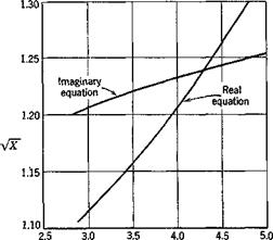
Figure 6.18 shows a plot of these roots vs. I/к. It is seen that the real and imaginary equations are both satisfied at the intersection of the curves:
1=4.31, Vx = 1.239 (11)
Hence, the corresponding critical flutter speed
U„ = — 162 ft per sec (12)
kVX
Only the smaller of the two roots VX of the real equation is listed in Table 6.2 and plotted in Fig. 6.18. The larger of the two roots of the
|
1№ Fig. 6.18. Example 1. |
real equation forms a branch that does not intersect the curve for the imaginary equation. Hence, the above intersection is the only intersection, and the critical flutter speed given by Eq. 12 is the only critical speed.
A different point of view is to consider the flutter determinant not as two real equations but as a single equation for the variable X. For each assumed value of k, this equation may be solved for X. Since the coefficients are complex functions of k, the roots are, in general, complex. But X, by definition (Eq. 1), must be real to have a physical meaning. Hence, we must find the particular value of к that renders the root X real. A plot of the real and complex parts of the roots X with к as a parameter
will indicate whether such a solution exists. If the fluid is compressible, the calculations must be repeated for different values of the Mach number M. The correct M’s are those for which the assumed values and the calculated values agree.
In practical application, it is more convenient to use a different variable than X. Note that со2 and g always appear together in the flutter determinant as (co»2(l + iga), etc. For small values of gh, ga, gp, we may write
1 + iga = 1 + igh + Kga. ~ gh) = (1 + igh)[ 1 – Г Kga ~ gh)] (13)
provided that gh(ga — gh) is negligibly small in comparison to gh. Hence, let
z=(5)’a + fe) (и.
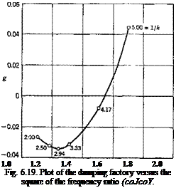
Then the flutter determinant (Eq. 21 of § 6.10) can be written as a cubic equation in Z. For a given k, the (complex) roots Z can be found. If we plot the roots Z with their real parts (сох/ш)2 as the abscissa and the ratios of the imaginary part to the real part, gh, as the ordinate, we obtain a parametric curve showing the variation of Z with k. The correct values of к at which flutter is possible are those that correspond to the value of gh of the specific structure. The compressibility effects, if any, must be catered for as before.
Example 2. For the torsion-bending flutter of the numerical example 1 considered above, the determinantal equation for 1 jk = 2 is given by Eq. 8. It is a quadratic equation because only two degrees of freedom are allowed. Equation 8 is derived for g = 0. When g Ф 0, we must replace X by Z as defined by Eq. 14. Hence for 1 jk = 2, and assuming gn = g« = g> we have
320.283Z2 + 74.463/Z – 1360.393Z – 99.836/ + 1110.312 = 0 (15) This is of the form
aZ2 + bZ+c = 0 (16)

![]() Vb2 — Лас
Vb2 — Лас
2 a ’ ~J<-) 2a
Denoting the two roots of Eq. 15 by Z(+) and Z(_> as in Eqs. 17, we obtain Z(_) = 1.1051 – 0.0303/, Z(+) = 3.1424 – 0.1960/
By repeating this process for several other assumed values of Ijk, Table 6.3 is obtained.
|
1 Ik |
z(_, |
Im(Z,_,) 8 R1 (Z,_,) |
zl+) |
|
2 |
1.1051 -0.0303і |
– 0.0274 |
3.1424 – 0.1960/ |
|
2.5 |
1.1842 – 0.0384г |
– 0.0324 |
3.1249 – 0.2647/ |
|
2.94 |
1.2390 – 0.0426г |
– 0.0344 |
3.1088 – 0.3344/ |
|
3.33 |
1.3134 -0.0411/ |
– 0.0313 |
3.0947 – 0.4059/ |
|
4.17 |
1.5023 – 0.0102/ |
– 0.0078 |
3.0723 – 0.5975/ |
|
5.00 |
1.7042 + 0.0745/ |
+ 0.0437 |
3.0911 – 0.8568/ |
|
Table 6.3 /1 = 40, b = 30,ft, со/ = 2.41 |
Clearly the imaginary part of Z<+) remains negative for all values of k. On the other hand, the sign of the imaginary part of Z(_t changes at certain value of k. According to the definition of Z (Eq. 14), the real part of Z is (wjco)2. The imaginary part is (wjw)2g. Hence,
![]() Im (Z) 8 ~ R1 (Z)
Im (Z) 8 ~ R1 (Z)
 |
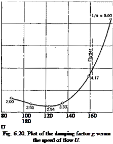
A plot of g vs. (wjco)2 with 1/k as a parameter is shown in Fig. 6.19. If
the value of g for the structure is zero, the critical condition is reached when
![]() – = 4.3]
– = 4.3]
The flutter speed is therefore
the function g can be plotted against U. The result is shown in Fig. 6.20.
This method was used by Smilg and Wasserman,6-20 and is sometimes known as “AMC” (Air Materiel Command) method. A tabular adaption for routine calculations has been published by Scanlan and Rosenbaum.619
 0.06
0.06
0.04
0.02 g
0
-0.02 -0.04
The values of to2 and g so obtained satisfy the flutter determinant, and determine a mode of flutter motion (i. e., the amplitude ratios and phase relations of h/b, a, /3, 6). Now suppose that, at a specific critical condition, the value of g is increased by imposing certain dampers on the wing; would this stabilize the wing? The answer is uncertain, because by the change in g the phase relationship between various components of motion changes. A new energy balance is set up, and it is not obvious whether
this results in a stable or unstable motion. In other words, an increase in damping does not necessarily raise the flutter speed.
Although the numerical example given above shows an increase in Ucr by an increase of g, examples to the contrary can be constructed. Collar (see Chapter 8 of Ref. 3.20) has shown, for the case of pitching oscillations of a frictionally constrained airfoil, and Frazer6 8, for the case of wing bending-aileron rotation, that it is possible to adjust the wing mass distribution in such a way that the flutter speed decreases by imposing several types of damping: dry friction, viscous damping proportional to amplitude, and damping force proportional to the square of the amplitude.*
It may be pointed out that the destabilizing effect of damping is not entirely unfamiliar in aerodynamics. For example, the origin of turbulence in a flow lies in the viscosity of the fluid.


