
Our heavyweight helicopter equal in the world does not have
In Rostov started production of the most load-lifting rotary-wing car The Russian holding «Helicopt[...]

Everything about aircrafts and helicopters. News and events in aviation worldwide. Civil, transportation, military helicopters and airplanes.

Everything about aircrafts and helicopters. News and events in aviation worldwide. Civil, transportation, military helicopters and airplanes.

Everything about aircrafts and helicopters. News and events in aviation worldwide. Civil, transportation, military helicopters and airplanes.

Everything about aircrafts and helicopters. News and events in aviation worldwide. Civil, transportation, military helicopters and airplanes.


A fundamental result of rotor dynamics emerges from the above analysis, that the flapping response is approximately 90° out of phase with the applied cyclic pitch, i. e., 01s gives в1С, and $1C gives ^1s. For blades freely articulated at the centre of rotation, or teetering rotors, the response is lagged by exactly 90° in hover; for hingeless rotors,
 -2 ——- 1—1—- 1 1—i. I i.—і————– 1—j
0.0 0.2 0.4 0.6 0.Є 1.0
(C) – tli’-!-.–
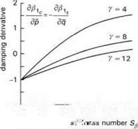
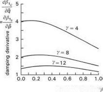
Fig. 2.21 Variation of flap derivatives with Stiffness number in hover: (a) control;
(b) damping; (c) cross-coupling
such as the Lynx and Bo105, the phase angle is about 75-80°. The phase delay is a result of the rotor being aerodynamically forced, through cyclic pitch, close to resonance, i. e., one-per-rev. The second-order character of eqn 2.22 results in a low-frequency response in-phase with inputs and a high-frequency response with a 180° phase lag. The innovation of cyclic pitch, forcing the rotor close to its natural flapping frequency, is amazingly simple and effective – practically no energy is required and a degree of pitch results in a degree of flapping. A degree of flapping can generate between 0 (for teetering rotors), 500 (for articulated rotors) and greater than 2000 N m (for hingeless rotors) of hub moment, depending on the rotor stiffness.
The flap damping derivatives, given by eqns 2.31 and 2.32, are illustrated in Figs 2.21(b) and (c). The direct flap damping, двіс/дq, is practically independent of stiffness up to Sp = 0.5; the cross-damping, д^1с/дp, varies linearly with Sp and actually changes sign at high values of Sp. In contrast with the in vacuo case, the direct flapping response now opposes the shaft motion. The disc follows the rotating shaft, lagged by an angle given by the ratio of the flap derivatives in the figures. For very heavy blades (e. g., y = 4), the direct flap response is about four times the coupled motion; for very light blades, the disc tilt angles are more equal. This rather complex response stems from the two components on the right-hand side of the flapping equation, eqn 2.22, one aerodynamic due to the distribution of airloads from the angular motion, the other
from the gyroscopic flapping motion. The resultant effect of these competing forces on the helicopter motion is also complex and needs to be revisited for further discussion in Chapters 3 and 4. Nevertheless, it should be clear to the reader that the calculation of the correct Lock number for a rotor is critical to the accurate prediction of both primary and coupled responses. Complicating factors are that most blades have strongly nonuniform mass distributions and aerodynamic loadings and any blade deformation will further effect the ratio of aerodynamic to inertia forces. The concept of the equivalent Lock number is often used in helicopter flight dynamics to encapsulate a number of these effects. The degree to which this approach is valid will be discussed later in Chapter 3.
