Influence of Projection Parameters
The spatial coupling methods available in the ACM all base the transfer of loads and deformations on geometric neighbourhood relations between the wetted surface and the structure. For this, the methods require different additional interpolation parameters. As explained in Chap. 3.2, the FIE method for beam elements has three additional interpolation parameters: The weighting parameters ^ljmit and dlimit apply for projections of surface points in the vicinity of kinks of the beam model. The width of the intersection region alimit has to be defined if assemblies border on each other. For shell and volume models, the FIE method currently does not call on interpolation parameters. Once it has been extended to configurations with multiple assemblies, aljmit also will come into play. The GSB and the MLS methods are derived from general interpolation algorithms. They require the definition of the (minimum) number of supports Ng or NM, the number of additional support points per edge midpoint nFB, their radius rFB, the polynomial degree of the interpolation functions (7) or (11) and the type of RBF function ф. The MLS method is also suitable for configurations with multiple assemblies and thus again alimit has to be provided. None of these parameters is directly based on physical considerations, so the optimal values are not obvious.
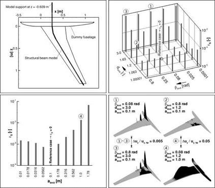
All interpolation parameters of the FIE method required for beam models shall be examined here, whereas for the MLS and GSB methods only a selection is presented in detail. As became clear from the results presented in Chap. 4.1.2, distinct load distributions can result in identical deformation distributions. Therefore, the influence of the projection parameters is evaluated via the deformation projection. In order to have identical input data for all cases, no aerodynamic loads are imposed on the wetted surface. Instead, a force distribution is applied directly to the structural nodes. The structural deformations then become independent of the projection method. The differences in the shape of the wetted surface can consequently be attributed solely to the deformation projection. Also in this investigation exact reference solution is not available, and as in the previous chapter the deviations should not be interpreted as absolute errors.
|
Fig. 11 top left: Planform of the HIRENASD wing and its structural beam model. The model support is outside the pane at z = —0.609 m. The dummy fuselage is not physically connected to the wing. It is also represented as a component in the beam model, but its nodes are all clamped. top right: RMS deviations of the wetted surface deflections relative to those obtained with the default settings. The parameters Дм and 4m are varied and amt is kept constant at 0.1 m. bottom left: RMS deviations of the wetted surface deflections relative to those obtained with the default settings. aumit is varied, while the remaining parameters are kept constant at Дм = 0.08rad and dlimit = 1.2. bottom right: Distributed values of the normalised deflection difference Auy/uy, tip | for the four parameter combinations marked in the top right and bottom left diagrams. |


