Lifting-Line Concept
In both the thin-airfoil analysis and the numerical methods discussed in Chapter 5, the tangency-boundary condition was imposed along the mean-camber line or along the surface of the airfoil to generate a solution. The same is true in the numerical methods for three-dimensional wings, discussed later in this chapter. However, in the lifting-line theory that follows, a different approach is taken.
In the lifting-line analytical model, the vorticity representing a wing is collected into a single finite-strength vortex extending spanwise from wing tip to wing tip. Such a model leads to a simple solution of acceptable accuracy, providing that certain restrictions are placed on wing planform. If this analysis is to give satisfactorily accurate results, then the wing must be of relatively large aspect ratio (usually greater than 4 or 5) and the wing planform should not have a large taper or sweep. The reason for these restrictions becomes apparent as the theory develops. Because the wing is to be represented by a single spanwise vortex, the resulting theory does not supply any chordwise pressure-distribution information. However, the theory predicts forces on the wing satisfactorily through the vortex theory of lift.
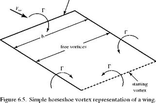
The line vortex containing the combined chordwise circulation of the wing is termed a lifting line. It is also termed a bound vortex because it is fixed at the location of the wing in the stream and is not free to move. In accordance with the second Helmholtz theorem, this bound vortex cannot end at the wing tips. Thus, the lifting line is turned in a downstream direction at the tips and the two vortices trail downstream (Fig. 6.5). These two vortices have a physical counterpart (see Fig. 6.3): namely, trailing vortices generated at the wing tips. The two trailing vortices are termed free vortices because they are free to move and do not represent a fixed solid surface. The resulting U-shaped vortex system is termed a horseshoe vortex because of its shape.
The horseshoe vortex is designed to close on itself by closing the end of the horseshoe with another vortex (see the dashed line in Fig. 6.5). This has a physical reality, representing the starting vortex discussed in conjunction with twodimensional airfoils and the Kutta condition in Chapter 5. In a steady-flow problem, this starting vortex is far downstream and does not affect results at the wing because of the 1/(distance)2 influence. Thus, the horseshoe vortex alone may be used to model flow over a finite wing.
|
bound vortex
|
Vortex Sheet
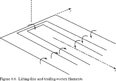
The vortex model in Fig. 6.5 is too simple and does not represent physical reality. If the circulation, Г, is constant across the span—as it must be to satisfy the first Helmholtz theorem—then according to the Kutta-Joukouski Theorem (see Chapter 4), L’ = рУтеГ, and the lift per unit span must be constant across the span up to the wing tips. However, the lift is caused physically by a difference in surface pressure between the lower and upper wing surfaces; this pressure difference must be zero at the wing tips because there is no physical barrier between the two surfaces. Accordingly, the lift must go to zero at the wing tips. This contradiction is resolved by representing the wing by a lifting line consisting of a bundle of vortex filaments of different lengths (Fig. 6.6). The lifting line is now of variable strength spanwise. Each of the bundled filaments must be a horseshoe vortex, so that a number of vortex filaments trail downstream. In the final model, there is an infinite number of such filaments, each of infinitesimal strength, and the trailing filaments form a trailing – vortex sheet. In Fig. 6.6, only a few vortex filaments are shown, for clarity.
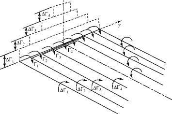
Before deriving the equation for calculating the induced velocity at the lifting line, the model given in Fig. 6.6 must be made more precise. Consider the lifting line as consisting of four vortex filaments (Fig. 6.7). Each bound-vortex filament has a different length and has a strength given by Гп. The lifting line then has a variable strength, ranging from Г1 at the wing tips to Г4 at the plane of symmetry, where:
Гі = АГ!
Г2 = АГ1 + АГ 2
Г3 = АГ1 + АГ2+ АГ3 (6.5)
Г4 = АГ і + АГ 2 + АГ з + АГ4.
Because each bound filament is part of a horseshoe vortex, four vortex filament pairs trail downstream. Because all three legs of the horseshoe vortices must have the same strength, the trailing vortices each have the same strengths as the bound filaments from which they trail.
4
|
|
![]()
|
|
|
|
|
|
|

ДГ = Гі
ДГ2 = Г2 – Гі
АГз = Гз – Г2 (6.6)
ДГ4 = Г4 – Г3.
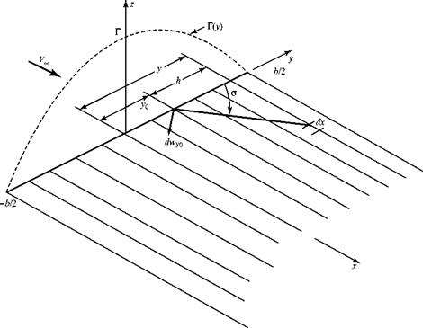
Now, we imagine that there are an infinite number of bound filaments, each of a different length and each of a different infinitesimal strength dr. In the limit, the stepwise distribution along the lifting line becomes continuous (Fig. 6.8) so that Г = Г(у). We notice from Fig. 6.7 that the trailing-vortex filament strength is given by the difference in bound circulation across a spanwise interval at the point of origin of the trailing filament. With a continuous distribution of bound circulation, ДГП ^ dF. The difference in bound-circulation strength at any spanwise location for an incremental spanwise step dy is given by ДГП = ДГ = (АГ/Ay)Ay or, in the limit, by:
dГ
dT – = – dy-ydy – («)
This equation states that the strength of the vortex filament depends on the span – wise gradient of the bound vorticity.
A continuous spanwise distribution of circulation (i. e., lift per unit span) and the resulting trailing-vortex sheet is shown in Fig. 6.8.
Although the distribution of Г(у) in Fig. 6.8 is yet to be found, if the wing is symmetrical about the root chord, then Г(у) must have the general shape shown in the figure because L’ goes to zero at the wing tips, where the pressure difference across the wing bottom-to-top goes to zero. Equation 6.7 then makes physical sense: It states that the vortex filament trailing from the wing at y = 0 has zero strength (i. e., no spanwise-velocity-component mismatch, by symmetry), whereas the trailing
|
Figure 6.8. The lifting line and vortex sheet. |
filaments near the wing tips have the greatest strength (i. e., largest spanwise velocity component mismatch at the trailing edge).
In Fig. 6.8, the spanwise distribution of circulation is shown as symmetrical about mid-span. This is the usual case because wing planforms normally are mirror images of one another about the centerline of a vehicle. An exception is the case in which the ailerons (i. e., small control surfaces located near the wing tips) are deflected asymmetrically to generate a rolling moment. Another exception is a study of the wing aerodynamics if one wing-flap actuator failed. These effects can be accounted for by a more elaborate lifting-line treatment. Only the symmetrical case is considered here.


