Longitudinal Equilibrium
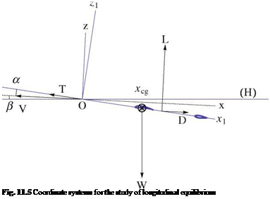
In this model, we consider the airplane flying at uniform velocity along a straight trajectory contained in a vertical plane. This corresponds to a steady situation, with no acceleration. The roll and yaw are both zero. Two coordinate systems are introduced: the aerodynamic coordinate system in which the x-axis is aligned with the airplane

velocity vector but oriented in the opposite direction and the z-axis upward; the other coordinate system is attached to the airplane, with the x1-axis along the fuselage axis and the z1-axis upward. The origin of the coordinate systems is placed at the nose of the airplane, see Fig. 11.5.
The incidence angle is the angle a = (Ox, Ox1), the slope angle is в = (H, Ox), both positive in the figure. The dimensionless coefficients, thrust, weight, lift, drag and moment coefficients are defined as
The lift force includes contributions from the main wing and the tail. The latter could be positive or negative, depending on the flight conditions. Note that the fuselage does not contribute to lift, according to slender body theory. The drag is evaluated with the best estimations of zero-lift drag, using flat plate formula for the wetted areas of streamlines elements, except for the main wing, and drag tables for the landing gear. The wing viscous drag is included in the wing viscous polar: The 2-D viscous polar has been obtained for a range of incidences corresponding to attached and separated flows with the well-known program XFOIL (or MSES for multi-element airfoils) of Dr. Mark Drela; the 3-D polar is derived from it, using Prandtl Lifting
|
Fig. 11.6 Double element geometry |
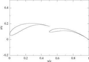
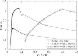
Line theory and the 2-D viscous polar at each span station. The 3-D polar is extended beyond stall. The induced drags of the main wing and the tail are included as well. The moment coefficient refers to the nose of the airplane. The geometry of the main wing double element profile is shown in Fig. 11.6, and the corresponding main wing 2-D and 3-D polars for the double element airfoil and wing (AMAT 2006) are shown in Fig.11.7 and compared with the 2-D polar of the Selig1223 airfoil at Reynolds number 200,000. It is interesting to note the high maximum lift coefficient of the Selig 1223 with Ci, max = 2.1 at this low Reynolds number and the even larger value achieved by the double element airfoil with Cl, max = 3.1. Note that the 2-D viscous
|
Fig. 11.7 Viscous polars for the Selig 1223 airfoil and the double element airfoil and wing |
drag of the double element is comparable to that of the S1223 drag near maximum lift up to Ci = 2.8. Another noteworthy point to make is the large induced drag of the AMAT wing which is a direct result of the medium wing aspect ratio AR = 8.75, indicating that at CL = 2.8, 88 % of the wing drag is induced drag.
The tail setting angle tt is the parameter that controls the equilibrium solution (trimmed equilibrium).
The longitudinal equilibrium equations consist of two equations for the forces and one for the moment. They read
CL + CT sin(a + t) — Cw cos в = 0 CD — CT cos(a + t) + Cw sin в = 0 (11.45)
Cm, o + TfCw cos(a + в) = 0
lref
Here, the propeller thrust makes an angle t with the airplane axis. There are three unknowns, the equilibrium incidence, aeq, velocity, Veq and slope, eeq. This is a highly nonlinear system, especially near the stall angle (maximum lift) since multiple values of a exist for a given CL. A combination of fixed-point iterations until close enough to the solution, followed by Newton’s iterations are needed to converge, when the solution exists, depending on the trim angle tt.
The equilibrium code is used concurrently with the acceleration result Vt.0.(M) to verify the feasibility of taking-off with a given total mass M. By “pulling on the stick”, or equivalently, by rotating the tail flap in the upward direction, the equilibrium incidence increases and the equilibrium velocity decreases. If it is possible to find a tail setting angle such that Veq < Vt.0. take-off can be achieved provided в > 3° and the incidence is not too close to the incidence of maximum lift. If all these conditions are fulfilled, it is possible to increase the mass of the airplane by adding payload weight thus increasing the possible score.


