Our heavyweight helicopter equal in the world does not have
In Rostov started production of the most load-lifting rotary-wing car The Russian holding «Helicopt[...]

Everything about aircrafts and helicopters. News and events in aviation worldwide. Civil, transportation, military helicopters and airplanes.

Everything about aircrafts and helicopters. News and events in aviation worldwide. Civil, transportation, military helicopters and airplanes.

Everything about aircrafts and helicopters. News and events in aviation worldwide. Civil, transportation, military helicopters and airplanes.

Everything about aircrafts and helicopters. News and events in aviation worldwide. Civil, transportation, military helicopters and airplanes.


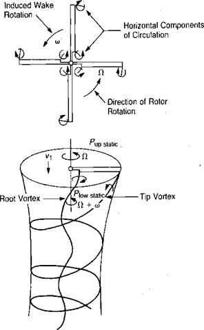
The wake has two effects operating on it that tend to produce rotation. One is the profile drag, which brings some air molecules up to the speed of rotation before losing them to the wake, just as a truck on the highway produces a following wake. The energy associated with this rotation is accounted for in the computation of profile power. The other cause of rotation is an induced effect that was not accounted for in the foregoing analysis. This rotation may be visualized by examining an idealized rotor wake made up of tip and root vortices which form helixes under the rotor. From Figure 1.28 it may be seen that the horizontal components of circulation in both the tip and the root vortices are oriented in such a manner as to induce wake rotation in the direction of rotor rotation. The equation for the energy associated with this induced rotation, or swirl, can be derived from momentum considerations similar to those used in the previous derivations. The figure shows a rotor wake that has no rotation above the disc but which has a rotation, 0), below it. The change in total pressure is:
|
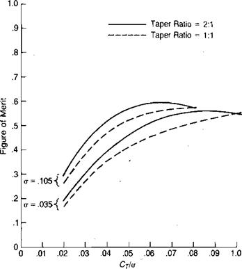
Source: Bellinger, “Experimental Investigation of Effects of Blade Section Camber and Planform Taper on Rotor Performance,” USAAMRDL TR 72-4, 1972.
= lAow„„C + ІР’Ї + 1Р(®Г)2] – [P„p»»,C + iP»f]
or:
Лр = Лр»»с + 5p(t*>r)2
The change in static pressure can be related to a change in induced power through the familiar induced power expression:
APi=ATvl
or
|
|
|
|
|
|
|
|
|
![]()
![]()
![]() P і, =T
P і, =T
‘thrust
The induced power associated with rotation is:
|
|
Assuming a uniform induced velocity, vb for this analysis:
which can be rewritten:
An expression for (0/Cl as a function of r/R can be derived by writing Bernoulli’s equation for air flow relative to the blade just above and just below the rotor disc:
or
Astatic = !pf2[2ft(0 ~ CO2]
but
Д/W = D. L. = pCr(M)2
 |
thus
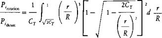 |
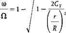
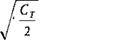
Note that (0 is imaginary if (r/R)2 < 2CT. To avoid this in the integration, the lower limit can be set to f2CT with little loss of validity:
The integral has been evaluated as a function of CT and is plotted in Figure 1.29. Also shown are the results of two more rigorous analyses from references
1.11 and 1.12, which were made with different assumptions but which resulted in nearly the same values as the approximate method. For the example helicopter in
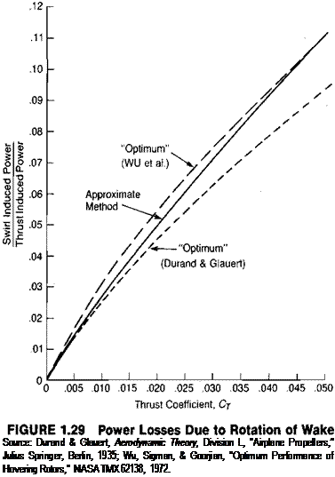 |
hover, the value of CT is 0.0073 and the corresponding induced power due to wake rotation is about 2% of that corresponding to thrust. This correction is marginally significant for this rotor but would be significant for more heavily loaded rotors or propellers used for static thrust.
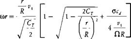
The aerodynamicist will occasionally be asked to calculate the rotational velocity in the wake to define conditions at the engine inlet and exhaust or in front of rocket pods. The equation for the induced rotation, (r(0)„ is
|
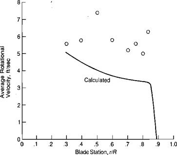
Blade Station, r/R
|
|
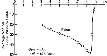
FIGURE 1.30 Vertical and Rotational Velocities at a Location.1 R below Rotor |
Source: Test points are from Boatwright, “Measurements of Velocity Components in the Wake of a Full-Scale Helicopter Rotor in Hover,” USAAMRDL TR 72-33, 1972.
The corresponding equation for the rotational velocity due to profile drag can be derived from the momentum equation in the annulus of Figure 1.18:
F = (m/sec)(Ai>)
or
dAD0 = (pAr2nry1)(cor)0
so that:
Using the fact that
 v i = ClR
 |
the induced and profile terms may be combined to give an equation for the rotational velocity at the rotor disc:
The equation can also be used below the rotor disc and for rotors that do not have ideal twist if the local induced velocity is used in place of vv For example, during the whirl tower tests reported in reference 1.4, both the vertical and the rotational velocities were measured at a location.1 R below the rotor. Figure 1.30 shows these measured velocities and the rotational velocity calculated from the vertical velocity. The correlation indicates that the method is adequate, at least for the region in which engines or rocket pods would be located.