SLIPSTREAM EFFECTS OF DUCTED PROPELLER AND FAN ENGINE ON WINGS
The reduced temperature of the efflux produced by ducted propellers and turbo fan engines has made it possible to direct their flow over the wing to increase lift. The lift increase produced by the wing due to slipstream effects is a function of the conditions in the slipstream,, which depends on the thrust loading of the engine. The data for combinations of fan engines is generally presented in terms of conditions in the slipstream which are different from those used for propellers and are given as follows:
Turbine Engine Definitions. The conditions in the slipstream of a turbo fan engine are described by the gross thrust which is
Gross Thrust = F^ = mj Vj (21)
where m/ is the mass flow at the engine nozzle exit and V/ is the jet exit velocity. Gross thrust is equal to the net thrust F when the engine is at zero velocity. Thus,, at V = 0
F9 = Fn (22)
Net thrust is the actual thrust of the engine and is equal to the change in momentum of the fluid passing through the engine. It is thus equal to the gross thrust minus the drag caused by accelerating the air being swallowed by the engine to the forward velocity of the engine. Thus, if the efflux of the engine were deflected, say 90°, to produce only lift, the mass of air handled times the free stream velocity would be drag. The net thrust Fn is the flight direction and is then
Fn = F^ cos £ – mc V0 (23)
where Є is the turning angle of the flow and mc is the mass flow handled by the compressor.
In some NASA reports F^ is used to define the axial force, the force along the x axis of the body, figure 1. This is taken to be the total force on the system, including the net force F-y, and the drag force D.
Since the gross describes conditions in the slipstream of the engine the other characteristics of the engine wing combination may be defined in terms of the coefficient C
Cm.= F<j /q S = T/qS (24)
where T = the static thrust of the engine and S the wing area, sometimes used as the semi span area. The dynamic pressure q is based in the free stream.
In comparing the effectiveness of the turning of various systems, the static-thrust recovery efficiency is used. This efficiency is defined by
V = + FM2 /Т (25)
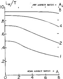
Ducted Propeller Wing Lift. A ducted propeller mounted in front of a wing arranged so that its efflux washes the upper and lower surfaces will also increase lift. Like an open propeller, the lift is increased due to the higher slipstream velocity and the increment is a function of the turning angle of the flow. Based on (6,b), ducted propellers can be expected to provide high lift augmentation as the increase improves with increasing jet aspect ratio and a corresponding decrease in the slipstream net thickness, figure 16. Thus it is desirable to use several small diameter jets, such as ducted fans, in front of a wing to produce the greatest lift augmentation for a given total thrust.
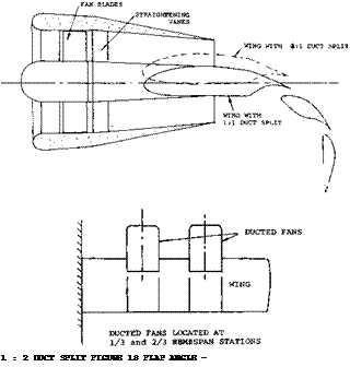
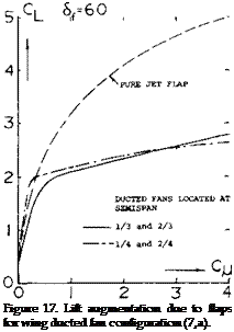
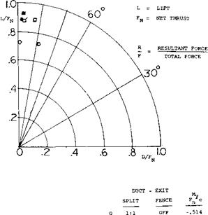
To obtain the required thrust at small diameters ducted propellers are needed for good propulsive efficiency. With ducted propellers the total wing can be immersed in the jet wake and flaps can be used to further augment the turning of the flow (7,a). As shown on figure 17, the basic wing lift is increased by the turning of the jet and an increase of circulation lift. A measure of the effectiveness of turning with the flaps set at 90° is given on figure 18. From this plot it appears that the best split of the wake occurs for Va above the wing. Here the greatest turning is obtained, along with the highest lift to thrust ratio.
|
Figure 16. Turning effectiveness of rectangular wings in static jets, ^ = 0. |
Wing Lift with Turbo Jet Engines. Like propellers and ducted fans, turbo jet engines can augment the lift of a wing to make possible reduced takeoff and landings with effective lift coefficients much higher than is possible with flaps. Since the size of the turbo jet engine is much smaller than the ducted fan and propeller, there are many more configurations that can be used to increase the wing lift. Possible configurations that have been considered are illustrated on figure 19 and include basically uriderslung engines with various flaps and engines mounted over the wing. Also included is the possible configuration where the engine is mounted directly in front of the wing.
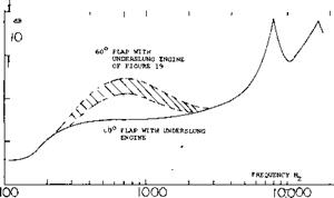
The configuration chosen will depend on the performance improvement possible, safety considerations, weight and the noise produced. With the underslung configuration the flap deflection will increase the noise level, figure 20. Since noise is an important consideration, especially with STOL aircraft, the choise of configuration will probably hinge on the level of noise produced.
6* 90
![]()
![]()
![]()
![]()
 a
a
a
CONTINUOUS
PITCHING MOMENT ABOUT 0.25 c ft/lb
Figure 18. Turning effectiveness of flaps on wing with a ducted fan.
(7) Ducted Fan Wing Interaction:
a) Newsome, W., Deflected-Slipstream Cruise-Fan Wing, NASA TN D-4262.
b) McKinney, Fan-Powered V/STOL Aircraft, NASA SP-116. [108]
Propulsion Lift Engines Over Wing. The need for noise reduction of STOL aircraft plus the indication that a wing could be very effective in turning the efflux of engines led to consideration of exhausting the flow over the wing upper surface. This system with low jet velocities can lead to a low noise configuration (9,c). A possible arrangement of such a system, figure 20,b, indicates that high turning efficiencies can be obtained along with large improvements of the total lift (9,a, b).


![]() The turning efficiency for flap settings of 20 to 60° nozzles of various aspect ratios are given on figure 23. Based on tests at the static condition the higher levels of turning efficiency appear to be for those cases where the flow spreads out on the wing forming a high energy jet that follows the wing contour. For instance, (9,b) when flap guide vanes were used on the aspect ratio 2 nozzle turning equivalent to a nozzle of aspect ratio 4 were obtained. Typical untrimmed lift drag and moment characteristics are given on figure 23 for the aspect ratio 4 nozzle and the flaps set at 60°. As with the underslung engines, the full potential of lift augmentation cannot be realized due to trim and engine out considerations. However, with further development this method of improving lift is expected to be highly competitive.
The turning efficiency for flap settings of 20 to 60° nozzles of various aspect ratios are given on figure 23. Based on tests at the static condition the higher levels of turning efficiency appear to be for those cases where the flow spreads out on the wing forming a high energy jet that follows the wing contour. For instance, (9,b) when flap guide vanes were used on the aspect ratio 2 nozzle turning equivalent to a nozzle of aspect ratio 4 were obtained. Typical untrimmed lift drag and moment characteristics are given on figure 23 for the aspect ratio 4 nozzle and the flaps set at 60°. As with the underslung engines, the full potential of lift augmentation cannot be realized due to trim and engine out considerations. However, with further development this method of improving lift is expected to be highly competitive.

Lift with Underslung Engines. By deflecting flaps directly in the efflux of a turbo fan engine very high operating lift coefficients (8,a) and Chapter 5 are obtained. As shown on figure 21, a maximum lift coefficient as high as 8 is possible with a C^of 3.5 and the use of a wing equipped with double slotted trad edge flaps and a leading edge flap. Associated with the high lift coefficient is a large diving moment so that the trimmed lift is lower, however. Because of the large lift coefficient the downwash at the tail becomes very large, requiring careful placement of the horizontal tail.
Typical operation of a wing with externally blown flaps is given in figure 22 from (8,e). In this case the wing is operated at lift coefficients considerably below the maximum to allow for an engine failure. This is a major problem in the design of augmented lift systems, as lateral moment also becomes very large due to the lift loss in area of the failed engine (8,d).
Although large values of CL are possible with underslung nacelle wing combinations, the practical aspects of safety, noise and trim reduces the lift advantages so that other configurations become more desirable.
|
Figure 20. Effect of Пар deflection on noise level for external blown underslung flaps. |
(9) Upper Surface Blown Jet-Flap:
a) Phelps, A., Wind-Tunnel Investigation, NASA TN D-7399.
b) Smith, C. C., Large-Scale Semispan Unswept Wind-Tunnel Test, NASA TND-7526.
c) Reshotko, Engine Over the Wing Nose, J of Aircraft April 1974.
(10) Effects of Jet Flow on Wings:
a) Putnam, Jet Flow on Wings, M = .4 to.95, TN D-7367.


