Our heavyweight helicopter equal in the world does not have
In Rostov started production of the most load-lifting rotary-wing car The Russian holding «Helicopt[...]

Everything about aircrafts and helicopters. News and events in aviation worldwide. Civil, transportation, military helicopters and airplanes.

Everything about aircrafts and helicopters. News and events in aviation worldwide. Civil, transportation, military helicopters and airplanes.

Everything about aircrafts and helicopters. News and events in aviation worldwide. Civil, transportation, military helicopters and airplanes.

Everything about aircrafts and helicopters. News and events in aviation worldwide. Civil, transportation, military helicopters and airplanes.


It is easy to invent a flying machine; more difficult to build one; to make it fly is everything.
Otto Lilienthal, 1848-1896
Lilienthal was a pioneer of gliding flight; however, the above quote makes the reader ponder whether he had the helicopter in mind when he wrote it. So far in this chapter, the road to the modern helicopter is anything but straight, so if we examine the quotation line by line, the concept of a lifting rotor constitutes the essential invention. Making it of large radius is simply taking advantage of Newton’s second and third laws, which guarantee that in generating a thrust force, by imposing a momentum change on the air, the use of a large quantity of air allows a low – speed change in the air which can be proved to be an efficient way of producing a thrust. When it comes to building the flying machine, the problems of directing it around the sky have to be thought out and translated into hardware: ultimately, however, the solutions for the helicopter are both straightforward and impressive. Upward lift is obtained with the rotor shaft essentially vertical; forward (or backward or sideways) propulsion is achieved by tilting the rotor plane in the desired direction (the rotor shaft itself is tilted in several early designs). This tilting of the rotor disc plane permits moments about the helicopter centre of gravity to be produced, which provides for manoeuvring. Here is a system more elegant in principle than that of a fixed-wing aircraft, where such integration of functions is not possible. However, the combining of several features of rotor control in one function causes its own difficulties.
One can pursue the helicopter rotor’s virtues one stage further by noting that the direction of airflow through the rotor becomes reversed in descent allowing blade lift to be produced without power (‘autorotation’), permitting a controlled landing in the event of engine failure. This is the point where the heredities of helicopter and autogyro merge and their place on the family tree is defined. These points were made by J. P. Jones in the 1972 Cierva Memorial Lecture to the Royal Aeronautical Society [1]. To quote him at this juncture:
Can we wonder that the conventional rotor has been a success? At this stage one might think the real
question is why the fixed-wing aircraft has not died out.
If we now return to Lilienthal we see the difficulty. Making the helicopter fly involves wrestling with a long catalogue of problems, some of which have been solved while there are others still to be solved – helicopters will always remain an intriguing challenge. During the gestation of the helicopter, it was necessary to invent the use of a tail rotor to stop the helicopter spinning round on the main rotor axis. To this is added other mechanisms of controlling the helicopter in yaw. It took the genius of Juan de la Cierva to devise a system of articulated blades to prevent the aircraft rolling over continuously – his earlier working life involved structures, where the use of a pinned connection to isolate moments provided an ideal grounding. While it can take off, land and hover efficiently, the helicopter can never fly fast judging by fixed-wing aircraft standards, the restriction, surprisingly enough, being one of blade stalling. Climbing is straightforward aerodynamically but descending involves a deliberate venture into the aerodynamicist’s nightmare of vortices, turbulence and separated flow. The behaviour of vortices left by an aerodynamic device is crucial to its performance and the locations of these vortices are critical.
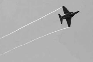
As an example, Figure 1.18 shows the location of a typical wake from a fixed-wing aircraft (AlphaJet) where the wing tip vortices stream behind the aircraft and are shown condensed water vapour acting as a tracer.
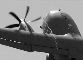
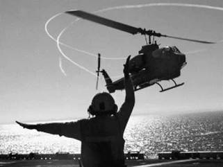
Figure 1.19 shows vortices being left by the propeller blade tips of an Alenia C27J aircraft and how they wash over the inboard wing structure. To examine a situation in the rotorcraft world, Figure 1.20 shows the vortex wake off a helicopter rotor (AH-1W). Close examination of the wake structure shows interaction with the tail rotor and the rear fuselage.
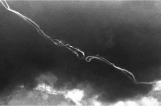
In addition to influencing any lifting surfaces, vortices interact with each other. Figure 1.21 shows the wake from the wings of a BAE Systems Hawk 200 aircraft after a tight pull-up
|
Figure 1.18 Tip vortices generated by a fixed-wing aircraft |
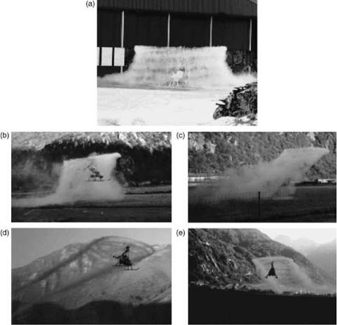
manoeuvre. The two tip vortices have closed together and on bursting (an unstable breakdown of the initial vortex structure) are beginning to form the characteristic loops associated with parallel pairs of vortices. Figures 1.22a-e show a sequence of images of a small helicopter with a tip-driven rotor. The tip jet uses fuel which produces a considerable amount of water vapour and, using this as a tracer, the exhausts show the wake structures in several different flight regimes.
Figure 1.22a illustrates a hovering condition close to the ground surface. The wake can be seen to contract immediately below the rotor but then expand as the downflow from the rotor is interrupted by the ground forcing it to spill outwards. This phenomenon is called ‘ground effect’ and is a very important feature of helicopter performance. The wake structure shows not only the ‘tube’ of vorticity, but also the individual blade tip vortices. Figure 1.22b shows the rotor at low forward speed. Ground effect is still present but the wake is now dispersed rearwards. As the forward speed increases, Figure 1.22c, the vortex ‘tube’ adopts a sheared profile for a short distance before mutual interaction between the vortices begins to distort the wake. The sheared
|
|
|
Figure 1.20 Rotor blade tip vortex trajectories (AH-1W) (Courtesy Safety Centre US Navy) |
vortex tube concept is a useful modelling technique but, with vortex interactions, as shown in Figure 1.22c, needs care in application. As forward speed increases further, the individual wake vortices show a cycloidal shape (in plan) and a roll-up character at the lateral rotor disc edges, not unlike a fixed wing. These characteristics are well shown in Figures 1.22d and e. In order to provide rotor control, previous discussion has highlighted the necessity of allowing the blades to move out of the plane of rotation. ‘Blade articulation’ is the term used for the use of conventional rotational hinges and this can lead to comparatively sluggish control since it is really the rotor thrust line change which can impart a turning moment to the helicopter, the free blade attachment hinges contributing very little. This can be significantly improved by adopting the principle of a hingeless rotor where the blade attachment is a flexible component. This can now provide a significant addition to the rotor thrust effect and obtain a greater turning effect for the helicopter. However, this situation isa double-edged sword since the improvement in the path for controlling the helicopter also applies to vibration and other adverse effects such as worsening aircraft
|
|
|
Figure 1.22 Rotor wake development (Courtesy ATI Corporation): (a) hover in ground effect (IGE); (b) hover IGE to out of ground effect (OGE); (c) low forward flight speed; (d), (e) high forward flight speed |
stability. With any practical combination of stability and control characteristics the helicopter remains a difficult and taxing aircraft to fly and generally requires autostabilization to restrict the pilot workload to a safe and comfortable level.
It would seem that we have on our hands a veritable box of tricks. What is certain, however, is that the modern world cannot do without the helicopter. It has become an invaluable asset in many fields of human activity and the variety of its uses continues to increase.
Moreover, to come close to the purpose of this book, the problems that have been solved, or, if only partly solved, at least understood, make good science, high in interest value. This, the book purports to show.
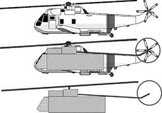
Up to the present, the single-rotor helicopter remains by far the most numerous worldwide and in this book we concentrate exclusively on that type. Its familiar profile, sketched in Figure 1.23, is the result of practical considerations not readily varied. The engines and gearbox require to be grouped tightly around the rotor shaft and close below the rotor. Below them the
|
Figure 1.23 The basic structure of a single-rotor helicopter |
payload compartment is centrally placed fore and aft to minimize centre of gravity (CG) movements away from the shaft line. In front of the payload compartment is the flight cabin. The transmission line from gearbox to tail rotor needs to be as straight and uninterrupted as possible. Put a fairing around these units so defined and the characteristic profile emerges.
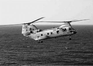
Of the other helicopter configurations, the tandem is the next to consider – a typical example, a Boeing Vertol H46 Sea Knight, is shown in Figure 1.24.
As shown in the figure, there are two rotors, placed at each end of the fuselage. They rotate in opposite senses so the aircraft will respond in yaw to the difference in torques from both of the rotors and a tail rotor is not used. The rear rotor is placed on a pylon so that in normal flight it is not immersed in the wake from the front rotor. This difference in rotation planes gives rise to interactions between translation and rotations during particular flight phases – but these are well known and appropriate action takes place. The figure shows the aircraft decelerating to a hover and to do this the entire aircraft is in a nose-up attitude. As can be seen, the rear rotor is
|
|
|
Figure 1.25 Mil 12 (Courtesy Agusta Westland) |
now moved towards the downwash of the front rotor and this can give rise to a sinking of the rear of the fuselage unless appropriate thrust changes are made. The location of the rotors at each end of the fuselage gives this configuration a wide CG range which for the single main and tail rotor configuration is very limited. The transmission is more complicated as the rotors must be kept in synchronization as the rotor discs overlap. Typically it consists of the engines supplying a combiner gearbox from which individual shafts supply the necessary torque to the rotors.
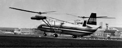
In the side-by-side configuration, there are a pair of contra-rotating main rotors, but in this configuration they are located laterally on pylons. Yaw control is by differential torque, but for this configuration the CG range is now in a lateral sense. A good example of this type is the Mil 12 shown in Figure 1.25.
This aircraft was designed, in the days of the Cold War, to carry large missiles and the lateral arrangement of the rotors gives a reduced interference between the rotors for an improved performance. The rotors require cross-shafting to keep them synchronized. The Mil 12 was described as appearing to swim through the air with the rotors advancing along the centre looking as if they are executing the breaststroke.
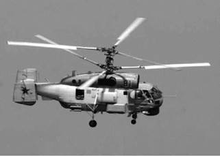
In the coaxial configuration, the rotors are contra-rotating but rotating about a common shaft. An example is the Kamov shown in Figure 1.26.
|
|
|
Figure 1.27 Kaman KMax (Courtesy Marcus Herzig) |
As can be seen, the rotor controls have to pass along the same axis so the upper rotor controls have to pass though those of the lower rotor. The rotors are articulated and so the effect of forward speed will tend to tilt the discs rearwards and laterally in opposition so that on one side of the rotor the blade tips are moving together. To avoid any chance of a blade clash, the rotor hubs are separated by a relatively long rotor mast. This gives rise to an increase in drag. With no tail rotor and a compact footprint, they are very useful in shipborne operations.
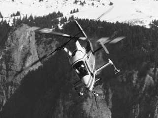
The helicopter company Kaman has for years used a dual-rotor system which occupies not much more than a rotor disc but uses two rotor shafts inclined to the aircraft’s central plane. The most recent of these aircraft is the KMax as shown in Figure 1.27.
The rotors have two blades and are phased by 90° which permits the rotors to pass without mechanical interference. Like the coaxial layout, this compact arrangement permits use in confined spaces. It has therefore contributed much effort in shipborne roles and those with very limited operational areas such as forestry.
The above discussion is concerned with proper helicopter types. If the restriction is lifted then other configurations can be examined, two of which are the tilt rotor and tilt wing.
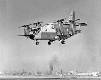
The classic tilt wing is the Ling-Temco-Vought XC142 as shown in Figure 1.28.
The rotor(s) have been replaced with propellers, two on each wing. The entire wing/engine/ propeller layout rotates through 90° so that vertical take-off and landing can be achieved with a conventional lifting through the propeller thrusts and revert to conventional wingborne flight by rotating the wing assembly back to horizontal. With the addition of wing devices such as flaps, the mechanical side of this arrangement is complex. The wing chord is always aligned with the propeller thrust line and so the slipstream can pass smoothly past the upper and lower surfaces. Transition is a difficult flight regime, particularly coming in to land when the wing is positioned with a high pitch angle and the supporting lift is being transferred to the propellers. Wing stall is a potential problem.
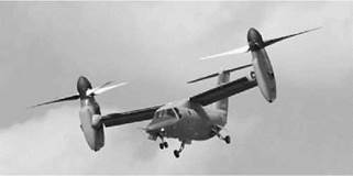
The more common tilt rotor variant only tilts the rotor/engine nacelle assemblies leaving the wing in a fixed position relative to the fuselage. The transition from the wing to the rotors is not applicable here, but in and around the hover, the rotor downwash is interrupted by the wing which will be close to a right angle to the flow. This will generate considerable download which
|
Figure 1.28 LTV XC 142 tilt wing (Courtesy McDermott Library, University of Texas) |
is exacerbated by the central parts of the downwash flowing inward along the wings and then forming a fountain flow which creates a larger download still. The use of wide chord flaps aligned vertically reduces the area facing the rotor downwash. A recent example of this type of rotorcraft is the Bell Agusta 609, shown in Figure 1.29.
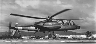
The final configuration to be highlighted within the helicopter family is the compound helicopter. There have been several companies who have pursued this variant, one of which, Piasecki, has already been mentioned in this chapter. Another landmark move into this type is the AH64A Cheyenne as shown in Figure 1.30.
This helicopter had a gyro-controlled main rotor; the tail rotor was located at the rear of a conventional tail boom alongside a pusher propeller. Stub wings were fitted to the fuselage, which gave this aircraft a fully compounded layout. They also provided an aerodynamic mounting for stores and ordnance.
Any further discussion of vertical take-off and landing (VTOL) configurations now leads into fan and jet lift which is moving away from the idea of rotorcraft and forms a natural halt to this discussion.
|
|
|
Figure 1.30 AH64A Cheyenne compound helicopter (Courtesy US Army) |