Transonic Flows
8.9.1 Onset of transonic flow
Any aerodynamic body has a maximum local velocity and local Mach number value somewhere near the surface which is greater than the freestream. Hence, as the freestream Mach number over a particular geometry at some angle of attack is gradually increased from small values, the maximum local Mach number max(M) will eventually reach and then exceed unity while the freestream is still subsonic, or < 1. The freestream Mach value when the threshold max(M) = 1 is crossed is called the critical Mach number
for that particular geometry and angle of attack. For potential flow over the body, the local Mach number field has the functional form M(r; MTO), so that the defining condition for the critical Mach can be stated as
max [ M(r; Mcrit) ] = 1
r
|
Cp*(MTO) = Cp(1; MTO) |
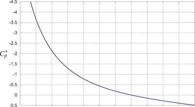
where in practice only the surface points r need to be examined for the maximum local Mach number. An equivalent criterion is in terms of the sonic pressure coefficient, shown in Figure 8.29, which is defined from the Cp(M; MTO) function (8.11) with M = 1 substituted.
An alternative definition for the critical Mach number is then defined as follows.
|
min [ Cp(r ; Merit) ] = Cp*(MTO)
0.3 0.4 0.5 0.6 0.7 0.3 0.9 1 1.1 1.2 1.3 1.4 Figure 8.29: Critical pressure coefficient vs. freestream Mach, for air (7 = 1.4). |
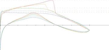
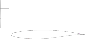
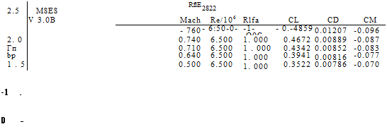
At the typical flight Mach numbers MTO ~ 0.7… 0.85 of jet transport aircraft, only modestly negative local Cp values of -0.75 …—0.3 are required to reach a local M = 1. Consequently, such aircraft necessarily have transonic flow over their wings. Figure 8.30 shows computed Cp(x) distributions for a typical “supercritical” airfoil designed to operate in the transonic condition, which occurs for MTO > Mcrit = 0.71 for this airfoil at this angle of attack. Larger angles of attack make the upper-surface Cp values more negative, and hence decrease Mcrit. In general, each airfoil will therefore have some Mcrit(a) or Mcr-lt(ct) dependency, depending on whether a or q is being held fixed as MTO is varied.
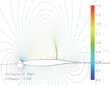
The supersonic region over the airfoil which appears in transonic flow is typically terminated by a normal shock wave, as described in Section 8.3 earlier in this chapter. The shock for the RAE 2822 airfoil for the MTO = 0.76 case is shown in Figure 8.31, along with the Mach waves or characteristics (see Section 8.8.2). These characteristic lines are defined by (8.133), except that the characteristic slope в is defined using the local supersonic M values ahead of the shock rather than MTO.
As MTO is increased beyond Mcrit, the shock wave strengthens and causes a very rapid increase in the overall profile drag. This is due to the increase in the shock’s own wave drag (see Section 8.3), and also due to the boundary layer being subjected to the intense adverse pressure gradient of the shock wave which increases the boundary layer’s downstream momentum defect. Consequently, economical transonic operation is feasible at a freestream Mach which is only slightly beyond Mcrit. The consequences for swept wing design will be discussed further in Section 8.9.3.
![]()
 |
|
|
|
|
