Wall Compatibility Conditions
In the continuum flow regime the no-slip condition at the surface of a body (tangential velocity components uw = ww = 0) is the cause for the development of the boundary layer. We assume for the following consideration preliminarily uw = ww = 0, and also that the normal velocity component at the body surface is zero: vw = 0, although vw/vref ^ O(1/Reref) would be permitted. We formulate
uy=o = 0, wy=o = 0, vy=o = 0. (7.47)
In addition, we can make statements about derivatives of u, w and v at the surface. The classical wall compatibility conditions for three-dimensional flow follow from eqs. (7.37) and (7.39). They connect the second derivatives of the tangential flow components u and w at the surface with the respective pressure gradients
![]() (7.48)
(7.48)
![]() d dw dp
d dw dp
^%)ly=° = d-Z-
The first derivatives of u and w at the surface in attached viscous flow are by definition finite. In external streamline coordinates, Figs. 7.1 a) and 7.2, we obtain for the main-flow direction
and for the cross-flow direction
lv=o£0. (7.51)
The first derivative at the surface of the normal velocity component v in у-direction is found from the continuity equation, eq. (7.36)
‘Л
^lv=o = 0. (7.52)
For hypersonic attached flow we generalize now the classical wall-compatibility conditions by taking into account (also in external streamline coordinates) possible slip flow (uw k 0, ww ^ 0), suction or blowing (vw ^ 0), and temperature gradients in the gas at the wall (dT/dyw ^ 0), assuming that all obey the boundary-layer assumptions. We find, again from eqs. (7.37) and (7.39)
The functions of the tangential velocity components u(y) and w(y) and their derivatives at the outer edge of the boundary layer in first-order boundary-layer theory are found from the asymptotic condition that the
boundary-layer equations approach there the (two-dimensional) Euler equations. From eqs. (7.37) and (7.39) we get

![]()
![]()
![]()
![]() uy=5
uy=5
wy=S
The normal velocity component v(y) is not defined at the outer edge of the boundary layer, nor its second derivative. From eq. (7.36) we find only the compatibility condition
The compatibility conditions permit to make assertions about the shape of boundary-layer velocity profiles. We demonstrate this with the profile of the tangential velocity component of two-dimensional boundary layers, Fig. 7.1 a), which also holds for the main-flow profile of three-dimensional boundary layers, Fig. 7.1 b). The result is particularly important for stability considerations of the laminar boundary layer (point-of-inflection criterium). We will come back to it in Sub-Section 8.1.3.
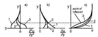
We consider three possible values of d2u/dy2w: < 0 (case 1), = 0 (case 2), > 0 (case 3), Fig. 7.4. We see that the second derivative (curvature) is negative above the broken line for all profiles given in Fig. 7.4 a). Hence the second derivative will approach in any case d2u/dy2y=g = 0 with a negative value, Fig. 7.4 a). It can be shown by further differentiation of the x-momentum equation, eq. (7.37), that for incompressible no-slip flow also
d3u.
^зІ«=о = 0. (7-58)
With these elements the function d2u(y)/dy2 can be sketched qualitatively, Fig. 7.4 a). Because we consider attached viscous flow, du/dyw > 0 holds in all three cases, Fig. 7.4 b). We obtain finally the result that boundary – layer flow in cases 1 and 2 has profiles u(y) without a point of inflection, and in case 3 has a profile u(y) with a point of inflection.
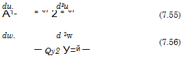
The interpretation of this result, Table 7.1, is found through a term by term examination of the generalized compatibility equation, eq. (7.53). It is assumed, that du/dyw is always positive, because we consider attached flow only. Also viscosity p and density p are positive. Since we deal with gas or a mixture of gases, the derivative of the viscosity with respect to the temperature is always positive: dp/dT > 0 (in liquids, especially in water, it is negative). The derivative du/dxw in the first term in the bracket of eq. (7.53) in the case of slip flow is assumed to be always negative, i. e., wall-slip is reducing in downstream direction. For convenience the term pw(du/dz)w, which can be relevant if slip flow is present, is not taken into account.
|
Fig. 7.4. Shape (qualitatively) of a) second derivative, b) first derivative, and c) function of the tangential velocity component u(y) of a two-dimensional boundary layer, or the main-flow profile of a three-dimensional boundary layer. Case 1: d2u/dy2w < 0, case 2: d2u/dy2w = 0, case 3: d2u/dy2w > 0. |
We see in Table 7.1 that the single terms in eq. (7.53) may or may not cause a point of inflection of the tangential velocity profile u(y). In any case an adverse pressure gradient causes it,[91] and also heating of the boundary layer, i. e., transfer of heat from the body surface into the flow, or blowing (normal injection [1]).
In a real flow situation several of the flow features considered in Table
7.1 may be present, this holds also for three-dimensional flow. Accordingly the sum of the terms in the bracket of eq. (7.53) is the determining factor. The individual terms may weaken or cancel their combined influence, or may enhance it. The factor 1/p, in front of the square bracket is a modifier, which reduces d2u/dy2w, if the surface is hot, and enlarges it, if the surface is cold.
In [1] it is shown that only in a few singular points streamlines actually impinge on or leave the body surface. This implies that in attached viscous flow close to the surface the flow is more or less parallel to the body surface. In closing this sub-section we use the wall compatibility conditions to determine the flow angle 0, Fig. 4.1, in the limit y ^ 0. We do this once more only for the profile of the tangential velocity component of two-dimensional boundary layers, Fig. 7.1 b), which also holds for the main-flow profile of three-dimensional boundary layers, Fig. 7.1 a).
With the no-slip condition eq. (7.47), the assumption of attached viscous flow with du/dyw > 0, and condition eq. (7.52), we find by means of a Taylor expansion around a point on the surface for small distances y from the surface
u x y, v x y2, (7.59)
|
Table 7.1. Generalized wall-compatibility condition for two-dimensional flow. Influence of the terms in eq. (7.53) on d2u/dy2w.
|
and hence
v
tan# = — oc y. (7.60)
u
The result is that when the surface is approached in attached viscous flow, the flow in the limit becomes parallel to it:
y 0: в 0. (7.61)
If we consider у and v as with ■/Reref stretched entities, the result permits us to generalize that the whole boundary-layer flow for Reref ^ <x becomes parallel to the surface. This observation is decisive in the derivation of the Orr-Sommerfeld equation, Sub-Section 8.1.2: the flow is assumed to be parallel to the surface. “Non-parallel effects” as well as “surface-curvature effects” are a topic of stability theory, too.


