Winglet Design
Winglets are small aerodynamic surfaces, placed at the tip of wings, to improve their aerodynamic efficiency. Many different wingtip device geometries have been proposed, including raked tip, blended winglet, canted winglet, up/down winglet, spiroid, tip feathers, tip fence, etc., see Bertin and Cummings Ref. [1]. In a seminal 1921 paper “The Minimum Induced Drag of Aerofoil” [2], M. M. Munk, using inviscid flow and lifting line theory, showed that the most efficient winglets are placed at 90° from the main wing. Such winglets, in the upward position (placed on the suction side of the wing), have been studied by JJC in a recent paper [3], using inviscid flow including a viscous correction. The reader is referred to the paper for the theoretical details. An optimization/analysis code has been developed to help students design winglets. For a given dimensionless winglet height at (in reference to half span b/2) and target lift coefficient CL, target, the optimization code calculates the optimum distribution of circulation along the wing span and the winglet, as a generalization of the lifting line theory to non-planar wings. The downwash is generalized as the normal wash, i. e. the component of the induced velocity normal to the dihedral shape of the wing. The 2-D polars for the main wing and the winglet can be different, corresponding to different profiles, with high camber for the wing and lower or no camber for the winglet (the choice made here). Once the circulation is known, a design can be selected since, as in inviscid flow, there is an infinite number of possible geometries that will produce the given circulation. One of the simplest strategies is to achieve a constant local lift coefficient C; by designing the chord distribution according to the local circulation and the root chord or the local desired lift coefficient Ci (aopt) (corresponding to maximum C; /Cd), as
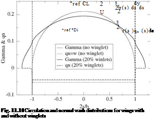
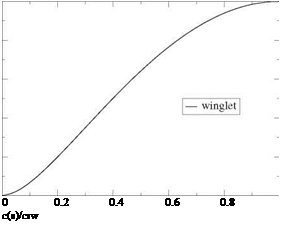
s is the curvilinear abscissa. For the main wing, aopt represents the effective incidence, i. e. aopt = a + ai, where a is the geometric incidence and ai the induced incidence. On the winglets, which are equipped with a symmetric profile, aopt = в = Ci, winglet /2п, represents the toe-in angle, since the induced normal wash is zero. In Fig. 11.10, a comparison of the optimum distributions of circulation and normal wash is presented for a simple wing and a wing with 20 % winglets, for a given lift coefficient CL = 2.0. The following comments can be made: the total lift is the same for both wings. The simple wing has an elliptic loading, with a high maximum root value, decreasing to zero at the tips, whereas the wing with winglets has a flatter distribution with lower root circulation and with higher loading at the winglet root. The downwash is constant for both wings, with a lower absolute value for the wing with winglets, which explains the lower induced drag given by
 |
|
where S = (1 + at )b/2 represents the curvilinear length of the non planar wing and qn (s) is the normal wash such that qn (s) = w(s) along the main wing, qn (s) = v(s) on the left winglet and qn (s) = —v(s) on the right winglet. The winglets carry a load which does not contribute to lift, since lift is given by
where y(s) represents the dihedral shape of the non planar wing, and dy/ds = 0 on the winglets. The winglets do not contribute to induced drag either since qn (s) = 0on the winglets. One should also note the flow singularity at the wing/winglet junction which shows as very large values of qn and requires a fine mesh system to capture the solution (200 points are used in this calculation). The induced drag of the wing with winglet, CDi = 0.0868, is compared to that of the simple wing, CDi = 0.106, which provides an 18 % decrease in induced drag and corresponds to an efficiency factor e = 1.22. The winglet geometry is shown in Fig. 11.11, where the chord distribution is normalized with the winglet root chord crw and the winglet height with atb/2. The winglet corresponds to the area located below the curve, the root being the bottom edge of the box and the trailing edge the right edge of the box.
1
 0.8
0.8
0.6
a
35
rl
0.4
0.2 0
Fig. 11.11 Winglet geometry


