Wings of small aspect ratio
For the wings of large aspect ratio considered in Sections 5.5 and 5.6 above it was assumed that the flow around each wing section is approximately two-dimensional. Much the same assumption is made at the opposite extreme of small aspect ratio. The crucial difference is that now the wing sections are taken as being in the spanwise direction, see Fig. 5.39. Let the velocity components in the (x, y, z) directions be separated into free stream and perturbation components, i. e.
(Uoo cos a + u Ux sin a + v’, w’) (5.70)
|
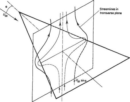
Fig. 5.39 Approximate flow in the transverse plane of a slender delta wing from two-dimensional potential flow theory |
Let the velocity potential associated with the perturbation velocities be denoted by ip’. For slender-wing theory ip’ corresponds to the two-dimensional potential flow around the spanwise wing-section, so that
![]() dV dV_
dV dV_
dy2 dz2
Thus for an infinitely thin uncambered wing this is the flow around a two-dimensional flat plate which is perpendicular to the oncoming flow component, sin a. The solution to this problem can be readily obtained by means of the potential flow theory described above in Chapter 3. On the surface of the plate the velocity potential is given by
![]() p’ = ±Uao sinasj(b/2)2 — z2
p’ = ±Uao sinasj(b/2)2 — z2
where the plus and minus signs correspond to the upper and lower surfaces respectively.
As previously with thin wing theory, see Eqn (4.103) for example, the coefficient of pressure depends only on vl = dpt/dx. x does not appear in Eqn (5.71), but it does appear in parametric form in Eqn (5.72) through the variation of the wing-section width b.
For the delta wing b = 2x tan A so that
Eqn (5.75) then gives
The drag is found in a similar fashion except that now the pressure force has to be resolved in the direction of the free stream, so that Cd ос sin a whereas Q, oc cos a therefore
![]() CD = Cl tan a
CD = Cl tan a
For small a, sin a ~ tana ~ a. Note also that the aspect ratio (AR) = 4 tanA and that for small a Eqn (5.76) can be rearranged to give
2тг tan A
Thus for small a Eqn (5.77) can also be written in the form
![]()
![]() 2СІ
2СІ
7Г (AR)2
Note that this is exactly twice the corresponding drag coefficient given in Eqn (5.43) for an elliptic wing of high aspect ratio.
At first sight the procedure outlined above seems to violate d’Alembert’s Law (see Section 4.1) that states that no net force is generated by a purely potential flow around a body. For aerofoils and wings it has been found necessary to introduce circulation in order to generate lift and induced drag. Circulation has not been introduced in the above procedure in any apparent way. However, it should be noted that although the flow around each spanwise wing section is assumed to be noncirculatory potential flow, the integrated effect of summing the contributions of each wing section will not, necessarily, approximate the non-circulatory potential flow around the wing as a whole. In fact, the purely non-circulatory potential flow around a chordwise wing section, at the centre-line for example, will look something like that shown in Fig. 4.1a above. By constructing the flow around the wing in the way described above it has been ensured that there is no flow reversal at the trailing edge and, in fact, a kind of Kutta condition has been implicitly imposed, implying that the flow as a whole does indeed possess circulation.
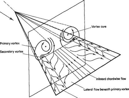
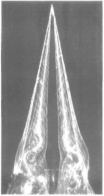
The so-called slender wing theory described above is of limited usefulness because for wings of small aspect ratio the ‘wing-tip’ vortices tend to roll up and dominate the flow field for all but very small angles of incidence. For example, see the flow field around a slender delta wing as depicted in Fig. 5.40. In this case, the flow separates from the leading edges and rolls up to form a pair of stable vortices over the upper surface. The vortices first appear at the apex of the wing and increase in strength on moving downstream, becoming fully developed by the time the trailing edge is reached. The low pressures generated by these vortices contribute much of the lift.
|
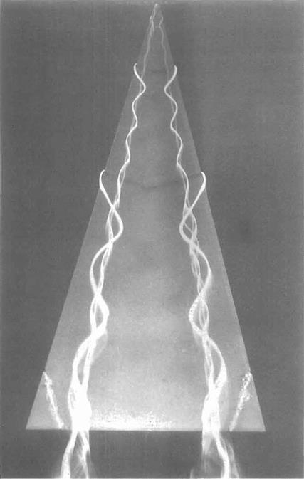
Pohlhamus[27] offered a simple way to estimate the contribution of the vortices to lift on slender deltas (see Figs 5.41 and 5.42). He suggested that at higher angles of incidence the potential-flow pattern of Fig. 5.39, be replaced by a separated flow pattern similar to that found for real flow around a flat plate oriented perpendicular to the oncoming flow. So, in effect, this transverse flow generates a ‘drag force’ (per unit chord) of magnitude
where Cdp has the value appropriate to real flow past a flate plate of infinite span placed perpendicular to the free stream (i. e. Cdp — 1.95). Now this force acts perpendicularly to the wing and the lift is the component perpendicular to the actual free stream, so that
This component of the lift is called the vortex lift and the component given in Eqn (5.76) is called the potential flow lift.
|
Fig. 5.41 Vortices above a delta wing: The symmetrical pair of vortices over a delta wing are made visible by the use of dye in water flow. The wing is made of thin plate and has a semi-vertex angle of 15". The angle of attack is 20° and the Reynolds number is 20000 based on chord. The flow direction is from top to bottom. See also Fig. 5.40 on page 264. (The photograph was taken by H. Werle at ONERA, France.) |
|
|
« – v ‘ ‘ mu* ^ V Potential flow lift Vortex lift |
The total lift acting on a slender delta wing is assumed to be the sum of the vortex and potential flow lifts. Thus
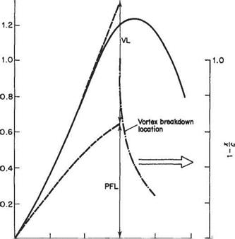
where Kp and K are coefficients which are given approximately by 2yrtanA and 1.95 respectively, or alternatively can be determined from experimental data. The potential-flow term dominates at small angles of incidence and the vortex lift at higher incidence. The mechanism for generating the vortex Uft is probably nonhnear to a significant extent, so there is really no theoretical justification for simply summing the two effects. Nevertheless, Eqn (5.80) fits the experimental data reasonably well as shown in Fig. 5.43 where the separate contributions of potential-flow lift and vortex lift are plotted.
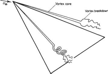
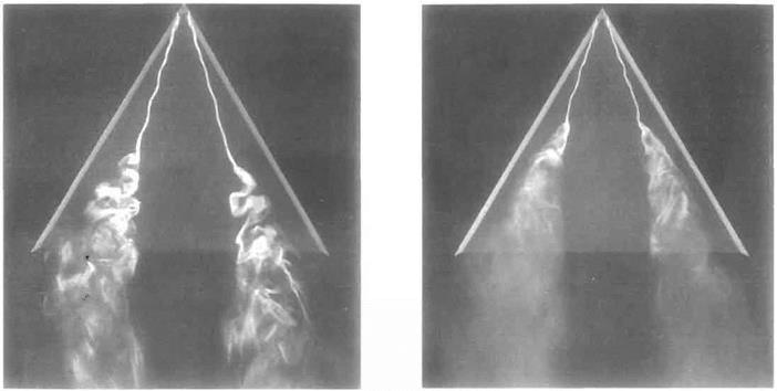
It can be seen from Fig. 5.43 that there is not a conventional stalling phenomenon for a slender delta in the form of a sudden catastrophic loss of Uft when a certain angle of incidence is reached. Rather there is a gradual loss of lift at around a — 35°. This phenomenon is not associated directly with boundary-layer separation, but is caused by the vortices bursting at locations that move progressively further upstream as the angle of incidence is increased. The phenomenon of vortex breakdown is illustrated in Fig. 5.45 (see also Figs 5.42 and 5.44).
|
|||
|
|||
|
|||
|
|
||
|
|||
|
|||
|
|
|
|
|
|
|
