Blade Element Method for Calculating the Power Required in Forward Flight Including Compressibility and Blade Stall
In order to develop a blade element method for calculating the power required in forward flight, it is necessary to consider the dynamics of the rotor and the trim of the helicopter.
Rotor flapping and blade pitch were discussed briefly in the beginning of this chapter.
The blade pitch angle в at any station x shown in Fig. 5-3 is usually given for a uniformly twisted blade as
6 = 0o + 0Tx + cos ф + 02 sin ф + Kpfl, (5-28)
where 90 = collective pitch,
6T = total twist, в і = lateral cyclic, в2 = longitudinal cyclic,
Kp = дв/dp = S3 effect.
Although the cos ф term is a maximum at ф = 0, 01 is the lateral cyclic pitch, for it gives rise to an aerodynamic flapping which lags it by 90° and is termed lateral flapping. A similar statement is true of 62; Kfi, the 63 effect, is the result of cocking the flapping axis of the blade so that its pitch is varied as the blade flaps.
The forward motion of the helicopter combined with cyclic control produces blade flapping defined by
P = Po — c°s ^ sin 0- — a2 cos 2ф — ■■■ (5-29)
where p0 = coning angle (independent of ф),
= longitudinal flapping, bi = lateral flapping, a2> b2, a3,… = higher harmonics.
For purposes of calculating the power required only first harmonic flapping is considered. It should be remembered that both the pitch and flapping angles are with respect to the disk plane, the plane normal to the rotor shaft axis. Observe that a positive value of results in a nose-up position of the tip-path plane with respect to the disk plane.
There are two dimensionless ratios ascribed to a given state of rotor operation: the inflow ratio Я and the tip speed ratio ц; ц is the ratio of the rotor translational velocity to the velocity at the tip due to rotation.
![]() V V
V V
o)R VT
 |
The inflow ratio X is similar to the advance ratio X used for propellers but should not be confused with it. The inflow ratio X is the ratio of the net velocity up through the disk plane to the tip speed. In order to calculate X,
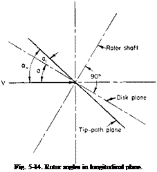
it is necessary to define one other angle, namely, a, the angle of attack of the rotor disk plane. This angle a is the angle between the incoming free-stream velocity and the rotor disk plane defined positively if the disk plane is nose-up; a and a1 are shown positively in Fig. 5-14.
If w is the downwash velocity at the rotor, then from Fig. 5-14 it can be seen that if all angles are assumed small
![]() . Va — w
. Va — w
a>R
Later we use an inflow ratio Av which is simply the ratio of the net velocity up through the tip-path plane to the tip speed. This is given by
(oR + 0l coR
or
Av = A + axfi. (5-32)
The angles в0, 0T, 9X, 02, fi0, au bx, a and the ratios fi and A, together with the thrust coefficient CT, are all interrelated. These relationships have been the subject of many investigations, a few of which are given in the references. The reader is referred in particular to Wheatley’s [10] original work.
Rather than discuss these investigations in detail, we present here in a simplified, easy-to-use manner, the results for a uniformly twisted, non – tapered blade. The thrust coefficient CT can be obtained simply as
ct = y [ЯГі + {во + K^o)T2 + °тТз + (02 “ *А)Г4].
But
w _CT
Vt~ V
Therefore
ct = {l+aj^a/4ll) 1>г1 + (fl. + kA)J2 + 0TT3 + (02 – (5-33)
where Tu T2, T3, and T4 are functions of ц and B, the effective dimensionless radius used in Chapter 4.
T, = ЦВ2 + in2), T3 = $B2(B2 + fi2),
T2 = ВЪ + fi2B, T4 = Ыв2 + in2).
a = section lift curve slope in Ct per radian, a = rotor solidity.
The above is obtained from an average thrust defined as that giving the same impulse per revolution as the time-varying thrust. In one revolution the differential thrust provides an impulse given by
or, since со = diji/dt,
1 Г2я dl = – dTdi/i; "Jo
|
‘2я _ 1_ f2* " / "Jo |
an average df is obtained from
or
![]() – 1 f2
– 1 f2
dT = — dT <іф.
2rtJ0
The coning angle can be obtained from
Po = 7f^F1 + (в0 + Kffi0)F2 + 9TFз + (02 – V,)F*] – r (5-34) where
|
F2 = jB2(B2 + /І2), F4 = i/cB3, cpaR* |

 |
F3 = B3(jB2 + У2),
The lateral flapping bx is given by
b = До-®и — (®i ~ (5-36)
where
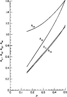
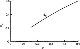
The coefficients Tu T2, Т3, Т4, Fu F2, F3, F4, А1Ь A12, A13, Аы, and Bu are given in Figs. 5-15, 5-16, 5-17, and 5-18 as a function of ц for an assumed В value of 0.97.
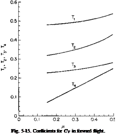 |
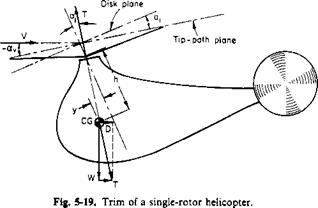
In addition to these relationships, it is necessary to consider the trim of the helicopter. A single-rotor helicopter is shown schematically in Fig. 5-19.
From this figure it can be seen that unless there is a trimming horizontal stabilizer or hinge-offset (to be discussed later) the thrust vector must pass through the CG and be equal and opposite to the resultant of the weight and the drag. (This assumes in the simplified case that the drag acts at the CG.) For small angles the result is obtained that
ZFC = 0 T аг W,
£FX = 0 .’. T( — a — Uj) = D,
or
<5-3T>
It can also be seen that if the CG is a ^-distance ahead of the rotor shaft and h below it then
(5-38)
Therefore
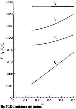 |
Although greatly simplified, the foregoing illustrates the procedure of calculating the longitudinal trim of a helicopter. In a tandem helicopter the equations must be modified to include the forces and moments due to both rotors. Some single rotor helicopters employ a significant amount of hinge offset to introduce a pitching moment proportional to the flapping. That such a moment can exist, consider a two-bladed rotor at the instant the blades are fore and aft, as shown in Fig. 5-20.
If F is the resultant force on any blade, then it can be seen from the figure that the instantaneous moment produced by the blade is
M = 2 FeRau
where e is the hinge-offset dimensionless distance from center to flapping hinge.
|
Fig. 5-17. Coefficients for first harmonic longitudinal flapping. |
|
Fig. 5-18. Coefficients for first harmonic lateral flapping. |
The average moment about the ф = тг/2 axis, as the blade travels around the azimuth, would be half this value for a two-bladed rotor.
Forces Acting on a Blade Element. The simplified theory of forward flight expressed by Eq. (5-27) was derived on the assumption that the drag
|
|
coefficient is constant, independent of r and ф. To improve on that assumption it is necessary to examine the various velocity components that influence a blade section. Consider Fig. 5-21 and refer to the side view. The disk plane, or plane perpendicular to the axis of rotation, is at an angle of attack a. Hence, in relation to the disk plane, a component Fa is going up through the disk. From Fig. 5-216 the velocity normal to the blade is cor,
|
Fig. 5-20. Rotor moment due to hinge-offset. |
plus a component of V, V sin ф. A component V cos ф is directed out along the blade. Now, looking at the plane containing the blade and the axis of rotation, we see that the component V cos ф directed out along the blade has a component down relative to the blade equal to Vfi cos ф. If the blade is flapping up at an angular velocity of /?, then, relative to the blade suction at a radius of r, a velocity is coming down equal to rfi. Also shown in this view is the downwash w which results from the thrust and the upward velocity Fa obtained from the side view.
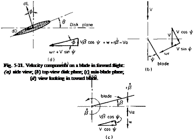 |
Finally, looking in along the blade at a section of it, we find that the total vertical downward velocity relative to the section is VP cos ф + w + rP — Fa. The component in the disk plane normal to the blade radius is
cor + V sin ф. Hence, if в is the pitch angle relative to the disk plane, the angle of attack of the section is
![]() VP COS Ф + W + rP — Vol
VP COS Ф + W + rP — Vol
cor + V sin ф
This can be made dimensionless by dividing by coR and remembering that
1 = [10L — w/VT.
 цР cos ф + x(P/co) — X X + Ц sin ф ’
but 0 and p were given previously by Eqs. (5-28) and (5-29). Therefore a = 0O + 9Tx + 0t cos ф + Q2 sin ф + K0O — cos ф)
цРо cos ф — (pat/2) – I – xat sin ф — X
X + Ц sin ф
In (5-40) ftjias been taken equal to zero from lateral trim conditions and a cos 2ф term has been dropped as a higher harmonic. The differential lift dL is given by
dL = pV2ecC, dr,
where
|
К — фс + A* sin Ф)2 + The differential drag is |
Ci = a0a,
dD = jpV2cCd dr,
where Cd = C/C,).
In terms of the differential lift, drag, and the angle ф, the average thrust and torque is
T = ~ J ~ VeC(C, cos ф – Cd sin ф) dr dф,
Q = J I Vecr(C, sin ф + Cd cos ф) dr сіф.
Dimensionless thrust and power coefficients defined according to Eqs. (5-2) and (5-3) can be determined from
CT = J j" (cicos Ф ~ Cd sin ф) dx thft, (5-41)
CP = — f2" f1 o(— x(C, sin ф + Cd cos ф) dx (іф. (5-42)
4л Jo Jxk VTJ
To do a more precise calculation, we would integrate Eqs. (5-41) and (5-42) numerically on a digital computer. The desired CT, given the weight ind tip speed, would be known. Also, by knowing the helicopter geometry, drag, and forward speed we could readily determine w, a, au and bv We would then calculate an approximate value of 60 from Eq. (5-33) and follow it by P0 from (5-34) and from (5-36). Equation (5-41) would then be integrated for CT. If the integrated value of CT did not equal the desired value, 0„ would be adjusted accordingly and the integration repeated.
In performing the numerical integration we would examine the section C, and Mach number at each ф and x; Cd would be chosen accordingly as a
function of C, and M. Of course, C, would be limited to a value of C,____
which would also be a function of M.
The assumption of a uniform downwash, w, over the disk is known to be in need of improvement. Although considerable effort has been expended by many on this particular question, there is still no accepted alternative. Reference 11, for example, multiplies w from Eq. (5-22) by the factor 1/(1 — 3^2/2) as a correction for the lateral dissymmetry in the Г-distribu – tion. However, Ref. 17 shows that this is incorrect and that the correction factor arose as the result of neglecting certain vorticity components in the derivation.
With the increasing availability of computers, the trend is toward precise stepwise numerical calculations which account in detail for the influence of the trailing vortex systems from all the blades. Reference 19 is an example of this approach.
Correction for Stall. Reference 11 presents an expression, CPs, for the addition to the power coefficient given by Eq. (5-25). This increment, CPt, is required to account for the increase in rotor torque caused by retreating blade stall. It is assumed that at the stall a jump of 0.08 occurs in the value of the section drag coefficient and that the rotor area within which blade stall exists is a pie-shaped segment of minimum dimensionless radius Xs symmetric about ф = Ъп/2.
Under these assumptions CPi becomes
![]() cP. = – d2(i – Wi – xl
cP. = – d2(i – Wi – xl
The dimensionless radius Xs, outboard of which blade stall is present, can be found by equating the section angle of attack of a general rotor section at ф = 270° to the angle of attack corresponding to C)ni>x. The angle of attack of a rotor section is given by Eq. (5-40).
 |
For the retreating blade ф = 270°, the equation immediately before Eq. (5-40) equated to 0:max becomes
![]() (5-45)
(5-45)
where В = ax – fidT – Г,
С = цГ -(- A,
It is necessary to modify the correction given by (5-43) for reasons that are now given. Reference 11 assumes a pie-shaped segment of the azimuth travel during which the blade is stalled (see Fig. 5-22).
 |
v
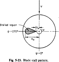
The correction CPs is a function of the dimensionless radius Xs, outboard of which the blade is stalled. This picture is satisfactory for the usual rotor. However, depending on the inflow ratio and blade twist, it is possible for the blade section angles of attack to be higher inboard than at the tip, which will result in the stall pattern shown in Fig. 5-23.
For the same value of Xs the stall pattern of Fig. 5-23 will obviously require less power than that assumed by Eq. (5-43).
The distance is the other root of Eq. (5-44):
![]() -В – УВ2 – 4втС
-В – УВ2 – 4втС
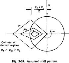 |
To correct Eq. (5-43) for this possible inboard stalling we assume that the stalled region is diamond-shaped. This is shown in Fig. 5-24 for varying values of p.
As. Xq approaches Xs, the correction for stall CPs must vanish. Similarly, as the average between X0 and Xs approaches unity, CPt must approach the value given by Eq. (5-43). This average, according to Eqs. (5-47) and (5-48) is
x±±xI= _B_
2 2вт
Thus a factor, ks, is defined, which multiplies Eq. (5-43) such that ks = 1 for — B/26T > 1 and decreases linearly to zero as — B/26T approaches Xs. Therefore
where
Compressibility Correction. A theoretical investigation of the effects of compressibility on the performance of a helicopter rotor in various flight conditions is given in Ref. 12. The results of this study show that regardless of p (for a p at least as low as 0.2 to as high as 0.5) the compressibility losses can be expressed as an increment in CP/o as a function of the amount by which the drag-divergence Mach number is exceeded at the tip of the advancing blade. It is also stated that experimental data show the drag
divergence Mach number to be approximately 0.06 higher than two – dimensional tests would indicate.
Thus from this report the following addition to the power coefficient can be formulated:
![]() CPo = ct[0.012A Md + 0.100(AMd)3],
CPo = ct[0.012A Md + 0.100(AMd)3],
where AMd = Mj( 1 + ц) — Mcrit — 0.06,
MT = coR/a0 — tip Mach number,
Mcrit = critical Mach number of advancing blade аіф = 90°. The angle of attack аіф = 90° can be obtained from Eq. (5-40).
![]() (5-50)
(5-50)
Although Eq. (5-49) is relatively simple, it gives results that are in apparent agreement with experimental data. Mcrit can be obtained from theoretical calculations of airfoil characteristics in Ref. 13.
Application of Equations
The previously developed equations are lengthy to apply to the calculation of the power required in forward flight. Fortunately, in these days of high-speed automatic computers this is not a serious objection. Most helicopter manufacturers have trim analyses programmed on digital computers so that for a given operating condition values of A, au fi0, 0o, and 62 can be readily obtained.
For purposes of preliminary analysis, however, an approximate trim analysis can be made. The application of the foregoing equations is perhaps best explained by the use of a specific example. Consider a fictitious singlerotor helicopter with the following characteristics :
Gross weight = 7000 lb.
Rotor diameter = 40 ft.
(oR = 650 fps.
a = 0.06.
/ = 16 sq ft = equivalent flat plate area. No hinge offset.
6T — —0.122 radians = —7°.
K, = 0.
t = 0.00228.
= 5.5.
Center of gravity on rotor disk axis.
![]()
 Rotor airfoil section = 0012 s
®max
In a more exact calculation, of course, account will have to be taken of the variation of amax with tip Mach number. We shall now calculate the power required by the helicopter operating at a speed of 120 knots at sea level. Initially, the power required by the antitorque tail rotor is not considered. However, it is covered later in more detail.
The power is calculated according to the simplified method. From Eq. (5-22)
T 7000
W z= ——————————- — ______________________________________________
2pVnR2 2(0.002378)(202)(1255)
= 5.8 fps.
From (5-23)
Pt = Tw = (7000X5.8) = 40,500 ft-lb/sec = 74 hp.
The parasite power can be calculated as
– DV – yv>f – ft002378f02)i|l6) – 156,000 ft-lb/sec
= 283 hp.
The profile power is obtained from
P„ = P 0(1 + 4p2).
The profile power P0 for /i = 0 can be determined from Fig. 5-4 and suitable corrections or calculated approximately as
aS° J-9 X CT
![]() = —^—г – d2—–
= —^—г – d2—–
Using the above, we obtain
T 7000
pAV2 ~ (0.002378)(1255X650)2
= 55.5 x 10“4.
Therefore
(0.06X0.0085) 9(0.008)(55.5 x 10“4)2
8 + 2 (0.06)
= 6.55 x 10⁻⁵.
 |
|||
From Eq. (5-10) and Fig. 5-4
Hence
P0 = pAVCPpi> = 0.002378(1255)6503(6.55 x 10’5)
= 53,600 ft-lb/sec = 97.3 hp.
Therefore, because p = V/V, = 0.31,
P„ = 97.3 [ 1 + 4(0.31)2]
= 135 hp.
Thus the total main rotor power required would be
p = 74 + 283 + 135 = 492 hp.
To determine the actual engine power required, it would, of course, be necessary to include the tail rotor power, the accessory power, the cooling power, and the transmission losses.
Consider now the additions to the power for retreating blade stall and compressibility effects.
First a check should be made to determine whether the blade is stalled or whether the critical Mach number is exceeded.
From Eqs. (5-50) and (5-44) it can be seen that this requires the determination of в0 and в2. It is assumed that there is no lateral flapping so that b2 = 0. Now for p = 0.31
|
Tx = 0.495, |
T3 = 0.245, |
|
T2 = 0.350, |
II p ел p |
|
Ац = 0.680, |
A13 = 0.660, |
|
A12 = 0.890, |
A1A = 1.21, |
|
A1S = 0.230. |
Equation (5-33), therefore, becomes
2 c
— = Я71 + Є0Т2 + ЄтТ3 + 02T4,
0.0323 = -0.0223 + O.35O0o – 0.0300 + 0.1502, or
O.35O0o + 0.1502 = 0.0846.
Equation (5-35) becomes
0 = лАц + 00^12 + ^Г^ІЗ + 02^14>
0 = -0.0306 + 0.8900 – 0.0805 + 1.2102, or
O.890Q + 1.210J = 0.111.
These equations can be solved to give
0O = 0.2957 radians = 17°,
02 = -0.1255 radians = -7.17°.
The terms for Eq. (5-45) are therefore
Г = -0.203,
В = 0.241,
С = -0.108.
Thus
xs = 0.712,
whereas
—0 ^ Xs = 0.985 and ks = 0.95.
The blade is stalled, with the additional required power being given by Eq. (5-43):
CPs = 14.5 x 10“5.
The section angle of attack at ij/ = 90° is obtained from Eq. (5-50) as
л
a90 = 00 + 02 + 0y H————— ^———
1 + Ц
= 0.0136 radians = 0.777 degrees.
Therefore Mcrit = 0.71 — 0.031 = 0.679. The tip Mach number is
![]() 650 + 202
650 + 202
1116
and
AMd = 0.765 – 0.679 – 0.06 = 0.026.
From Eq. (5-49) the additional power required to overcome compressibility losses is
CPc = 1.88 x 10~5.
Thus the additional power required to overcome blade stall and compressibility amounts to
Ahp stall = 216,
Ahp compressibility = 28.
The total horsepower required with the percentage breakdown is given in Table 5-1.
|
Table 5-1 Power Required Including Blade Stall and Compressibility
|


