Comparison with Experiment
 |
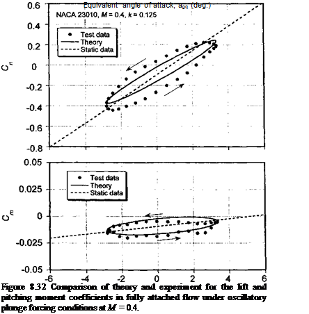
Whereas the formulation of the subsonic unsteady aerodynamic model in the previous section has been derived, in part, by using experimental measurements in the frequency domain, the validity of the model must be reconfirmed by comparing with experimental results of unsteady forces and pitching moments as functions of time or angle of attack. The unsteady airloads in response to an arbitrary time history of a and q can be obtained by using the previously derived indicial functions with Duhamel superposition in the form of the recurrence equations, or by integration of the state-space equations. Results will now be shown for both a pure plunging oscillation and also for a pitching oscillation; the absence of pitch rate in the plunge oscillations makes it possible to isolate the effects of the pitch rate in the unsteady aerodynamic response. For the plunging case, an equivalent
Angle of attack, a (deg.)
 |
|
quasi-steady AoA can be defined using
Notice that, unlike the pitch angle, the equivalent AoA in Eq. 8.182 is not a directly measurable quantity because it depends on the free stream velocity, V.
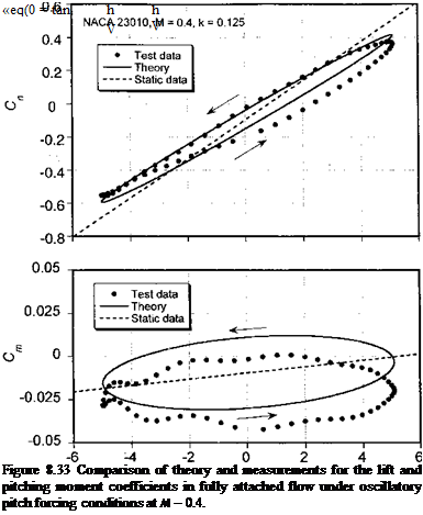
Representative variations in normal (lift) force and 1 /4-chord pitching moment coefficients are shown in Fig. 8.32 for harmonic plunge forcing and in Fig. 8.33 for harmonic pitch forcing. In each case, the results obtained from the subsonic unsteady aerodynamic model are compared to experimental measurements made by Liiva et al. (1968). The pitch and plunge data have been selected for approximately the same reduced frequency and mean AoA, although the equivalent amplitude of forcing is slightly different. The results show the expected characteristic elliptical shaped normal force and pitching moment loops symptomatic of attached flow. It is clear that in both cases there is a reduction of the unsteady “lift slopes” compared to the steady case, but with a larger phase lag (width of the hysteresis loop) for the plunging case. The width (amplitude) of the moment loop for the pitching oscillation is much larger than that for the plunge oscillation because of the

pitch rate contributions.[36] For each mode of forcing, it is apparent that the major axis of the unsteady pitching moment loop is closely aligned with the steady moment slope. This positive slope is a result of the aerodynamic center being slightly forward of the 1 /4-chord measurement axis.
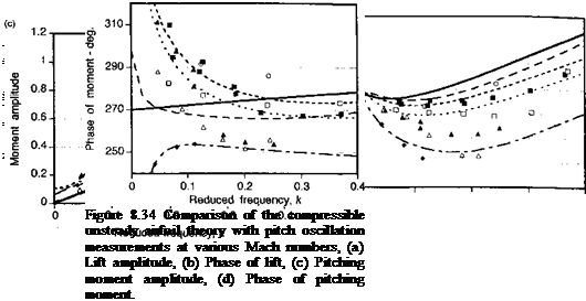
Further results showing quality of the predictions of the unsteady lift in compressible flow and the improvement that can be obtained over Theodorsen’s theory are given in Fig. 8.34 for pitching oscillations. To summarize as many operating conditions as possible, the results are shown in terms of lift and pitching moment amplitude and corresponding phase angle versus reduced frequency. To put the measurements on a common basis, the amplitudes of the response have been expressed as ratios by normalizing with respect to the measured static lift curve slope. Plunge oscillation data are more scarce, but as mentioned previously, they are particularly useful because of the absence of loading contributions from pitch rate (q) terms. It is clear from the results obtained in Fig. 8.34 that there is a good
correlation between the predicted and measured lift response. This provides considerable support for using this type of unsteady aerodynamic modeling over the Mach number and reduced frequency range appropriate for helicopter applications.
The subsonic compressible flow theory compares more favorably with measurements than Theodorsen’s theory, particularly for the phase. The pitching moment is, however, more difficult to predict without the use of empirical results. Notice from Fig. 8.34(d) that there is a gradual divergence of the phase angle as the reduced frequency tends to zero. As described previously in Section 7.7.1, this is attributable to an offset of the aerodynamic center from the 1 /4-chord moment reference point, and it emphasizes the need to carefully represent the changing aerodynamic center with Mach number in a rotor simulation if accurate predictions of the unsteady aerodynamic effects are to be obtained.


