Improved Mesh Deformation
Holger Barnewitz and Bernd Stickan
Abstract. An improved, robust, error reducing CFD-mesh deformation module for the parallel simulation environment FlowSimulator is presented. The mesh deformation method is based on radial basis function interpolation for the surface – and volume- mesh nodes combined with a group-weighting and displacement-blending approach. Since the latter weighting and blending approaches are based on given wall distances to the group surfaces, another module for the wall distance computation is introduced. Due to performance reasons, the number of input data locations (base points) used for the radial basis function interpolation must be limited. Therefore, methods have been developed to reduce the number of base points while keeping the interpolation error as low as possible. Furthermore, the modules have been parallelized for usage in multi-node high performance computing clusters. Finally, the capability of a multidisciplinary, parallel application is demonstrated in FlowSimulator with reduced errors and uncertainties.
1 Introduction
Airbus strategy to essentially move much more towards simulation makes it indispensable to know about any uncertainties and deficiencies in the predictive capabilities used for aerodynamic development. Knowing about error bands, their quantity and having in hand some means to manage and minimize their influence on the predicted results could tremendously help in the development process, reliable optimization of the product, shortening of development time and cost.
Holger Barnewitz • Bernd Stickan AIRBUS Operations GmbH,
Airbus-Allee 1, D-28199 Bremen
e-mail: {holger. barnewitz, bernd. b.stickan}@airbus. com
B. Eisfeld et al. (Eds.): Management & Minimisation of Uncert. & Errors, NNFM 122, pp. 219-243. DOI: 10.1007/978-3-642-36185-2_9 © Springer-Verlag Berlin Heidelberg 2013
 The MUNA project is an essential brick within the Airbus strategy of flight phy – sics/aerodynamics focusing on providing adequate tools for numerical qualification of aerodynamic design during concept phase. Respectively qualified CFD is expected to form the single basis for judgement of aerodynamic status before entering concentrated high level wind tunnel testing – to be ready for next new aircraft development. In addition, MUNA is contributing to support aerodynamic data process change towards "more simulation, less testing".
The contribution described in the following sections focuses on CFD mesh deformation used in the context of numerical aerodynamic shape optimization and shape design including static wing deformation. Major topics are:
• New mesh deformation module "FSDeformation" with advanced methods and integration into FlowSimulator [1]
• Geometry parametrization with a link between CAD (CATIA V5) and mesh deformation
• Use of mesh deformation for aerodynamic shape optimization
• Application of mesh deformation in a CFD/CSM coupled iterative process
• Combining shape design and CFD/CSM coupling in a multi-disciplinary optimization
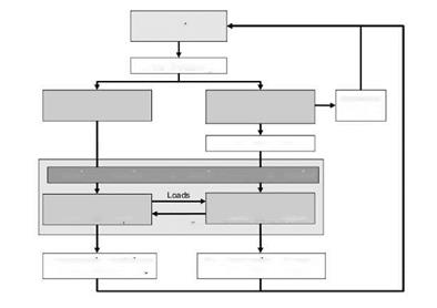
A typical multi-disciplinary optimization (MDO) process chain for shape optimization of a wing including the static deformation is shown in Fig. 1. An essential brick is the mesh deformation tool which is applied to:
1. reflect the changed shape design generated by a parametric CAD model,
2.
deform the wing according to aerodynamic (and other) forces.
New Geometry
New Beam Model
Fig. 1 Multi-disciplinary optimization chain for wing shape and structure weight
The advantage of using mesh deformation for unstructured grids is manifold:
• It avoids the problem of numerical noise for the calculated aerodynamic coefficients which might occur if new meshes are created for slightly changed geometries. This "noise" is caused by the change of mesh topology. Mesh deformation conserves the topology and small geometry variations produce small mesh deformations in a continuous way.
• A so-called restart capability of the flow solver allows to start from a flow solution calculated beforehand to save computing time.
• Usually, deformation of an unstructured CFD mesh is faster than re-generating a new mesh, and thus also saves computing time.
Mesh deformation plays a key role in aerodynamic shape optimization, since any adjustment of the model geometry has an impact on the 3D CFD-mesh. Because CFD-simulations usually rely on spatial discretization based on volume-meshes, these have to be updated if a CAD surface changes its location or its shape. The costs for the generation of new meshes should be as low as possible but should also produce usable grids even for large local changes in the model geometry. There are several possible ways to update the mesh, e. g. the complete re-meshing of the complete grid or the deformation of an existing grid.
For unstructured meshes, re-meshing would certainly change the topology of the mesh. Since the discretization in 3D space is generally not dense enough to produce a mesh-independent flow solution, the newly generated mesh would produce a slightly different flow field not caused by the geometry change. This leads, especially in the case of shape optimization, to noise in the aerodynamic coefficients, which often significantly disturbs the shape optimizer. Furthermore, the computational cost for re-meshing of unstructured grids is very high. Hence, mesh deformation is an essential tool in this area of computational fluid dynamics:
• the topology of the mesh remains unchanged and
• small geometry variations correspond to small changes of the numerically determined aerodynamic flow field.


