Prop Blade Drag
The propeller acts like any airfoil moving through the air, it produces an aerodynamic reaction due to its shape, angle of attack and velocity. The total reaction can be divided into vector components of lift and drag. It is the drag component of interest here.
Examination of Diagram 16, Forces in Cruise Flight, shows when the prop is operating at its maximum lift/drag ratio it is producing the most lift for the least drag. It follows, the
most thrust for the least amount of engine power used (the maximum thrust/torque ratio) will also be achieved at the maximum lift/drag ratio condition. Therefore, the prop will be operating at its maximum efficiency.
With the prop advancing through the air on its helical flight path, there is an upwash of air in front of the blade and a downwash behind, the same effect that occurs on an aircraft wing. The net result of this upwash and downwash is a general downwash of the relative air flow over the blade. Because the total reaction is at right angles to the relative air flow, it will be tilted rearwards from the vertical relative to the blade element. The horizontal component of the total reaction represents the propeller’s induced drag, or to use the modern terminology, trailing vortex drag. [See Diagram 1, Airfoil Terminology].
|
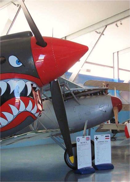
The Bristol M1c Bullet has a giant-size prop spinner looking very much like a doorbell. This aircraft is located in the RAF Hendon Museum, London. |
The pressure differential between the propeller blade’s top and bottom surfaces causes the air flowing over and under the blade to meet at the trailing edge at an angle to each other known as the ‘rake angle’. This causes a vortex sheet to emanate from each prop blade. High aspect ratio blades produce a smaller rake angle and therefore less induced drag than low aspect ratio blades. This again, reflects the superior efficiency of high aspect ratio blades. The flow around the blade from high to low pressure (rear to the front surfaces) causes the tip vortex to be stronger and cause more drag than the trailing vortex sheet. A similar vortex emanates from the blade root and this rotates in the same direction as the prop, while the tip vortex rotates in the opposite direction. The helical vortex sheet flowing off each blade affects the following blade by causing a disturbance in the air flow pattern resulting in a loss in efficiency: the greater the number of blades, the greater the disturbance. Using more blades negates the advantage of greater solidity, due to the increased flow disturbance.
On an aircraft wing, the vortex drag can be reduced by using an elliptical wing planform or by using wing taper, which has the same effect. However, the planform of a propeller blade has to be designed by calculation and is not necessarily elliptical. This is due to the difference in speed between the blade’s root and tip affecting a different amount of air mass in a given time. This problem is partly alleviated by using scimitar shaped blades as found on new generation turboprop aircraft. Scimitar blades are designed with extra chord width around the 50% prop radius station. At low speed during takeoff, more of the thrust is produced in this area of the blade. As the aircraft’s speed increases the major part of the thrust is produced further outboard along the curved span of the blade providing better efficiency at higher speeds where the effects of compressibility are delayed reducing drag and noise. This effect is akin to a swing-wing fighter aircraft.

|
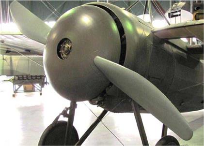
The propeller drag is caused not only by the blades, but also to a lesser degree, by the prop boss or shank. The blade roots, boss or shank cause profile drag due their inherent thickness. This is one reason for installing a prop spinner, to smooth the air flow over the drag producing area of the prop. At low speed ratios, the loss in efficiency caused by drag is around 10% rising to about 29% at higher speed ratios. The power required to overcome the profile drag is known as the ‘profile drag power loss’. Because aerodynamic forces are proportional to the square of the speed, it would appear obvious the thrust and torque would be at a maximum at the propeller tips where the rotational velocity is the greatest. However, this is not so. Due to tip losses caused by the spanwise flow along the blade towards the tips and also the effects of compressibility, thrust and torque values reach a maximum around the 75% prop radius station and decrease towards the tip. The blade chord is at a maximum around the 75% station for this reason, and this is the location of the minimum drag coefficient, as opposed to the maximum drag coefficient, which occurs at the blade tip due to induced drag and also at the blade root due to form drag, as mentioned above. The overall drag coefficient will remain approximately constant if the prop tips are not affected by compressibility
Sir Isaac Newton’s Third Law of motion states, “For every action there is an equal and opposite reaction”. In providing power to turn the propeller, the engine produces a torque component, which is a force acting in the same plane and direction as the propeller rotation. At a constant power setting, the engine torque is balanced by the equal and opposite force of propeller torque, in accordance with Newton’s third law. On an aircraft with a fixed-pitch propeller, the engine RPM will remain constant as long as these two forces remain in balance. A change of power setting or aircraft speed will change the value of the engine torque or propeller torque respectively. This will cause a change in the engine RPM. The same applies to a constant-speed prop but the CSU works to maintain a constant RPM masking the changes in prop or engine torque, which varies as the RPM squared. The total drag forces or torque of the propeller act through the centre of pressure of each prop blade. The prop torque can be found from the following formula:
Prop torque = kQpN2D5
Where kQ = torque
p = air density N = RPM D = Diameter


